Not long ago I acquired a TC Electronic Mojomojo on ebay in perfect conditions. I love the brand and wanted to try their analog overdrive pedal. I liked it and kept it, some people complain it is bland, or dark, or anything, but I think in the right ecosystem it can perform very well. I have to confess that it has only be used a few times, just because lately I am using my modified DS-1, BOSS OD-3 or Tim Pierce Overdrive. Maybe I have too many overdrives?
Yesterday I put it on my home pedalboard for some recording, and it sounded really really bad, with very low volume and an unbearable noise. Ok, let’s fix it. Oh, well, it is SMD! Do you know what SMD is? Those pretty boards with tiny little minuscule components. They are not easy to troubleshoot or fix, components are too close together and are not mounted through holes but soldered right on the surface (hence the name: Surface Mounted Devices).
This was not the first time I fix a SMD circuit, I have replaced some USB connectors, and not long ago I fixed a black MXR 6 band equalizer bought broken on ebay. Not impossible, but as I mentioned, components are very small, the board is usually multilayer, and soldering and desoldering is not easy. To make things a little harder, I couldn’t find Mojomojo schematic. When I bought it, I immediately opened it to see what was inside, and although didn’t have the time to trace the complete circuit, I could see it is based on soft symmetrical clipping with four bipolar diodes, a là Vemuram Jan Ray, Tim Pierce, Blue Note, to mention some.
After tracing the clipping operational surroundings and testing the implied components, could see that one of the diodes was behaving abnormally. The oscilloscope gave different lectures for the connection between diodes of the two clipping sections (positive and negative), and it could be explained by a faulty diode. Some additional tests and the diode was located. I was lucky because if the problem had been on some capacitor or in the tone stack it would have been much harder to fix.
Now the problem was that I didn’t have SMD diodes, I am in quarantine because of coronavirus and wanted to fix it soon. So, why not making a virtue of necessity and try some modification of the pedal?
First I soldered a conventional through hole bipolar diode similar to the faulty one to confirm that it was the only problem around, with success. The pedal was alive again.
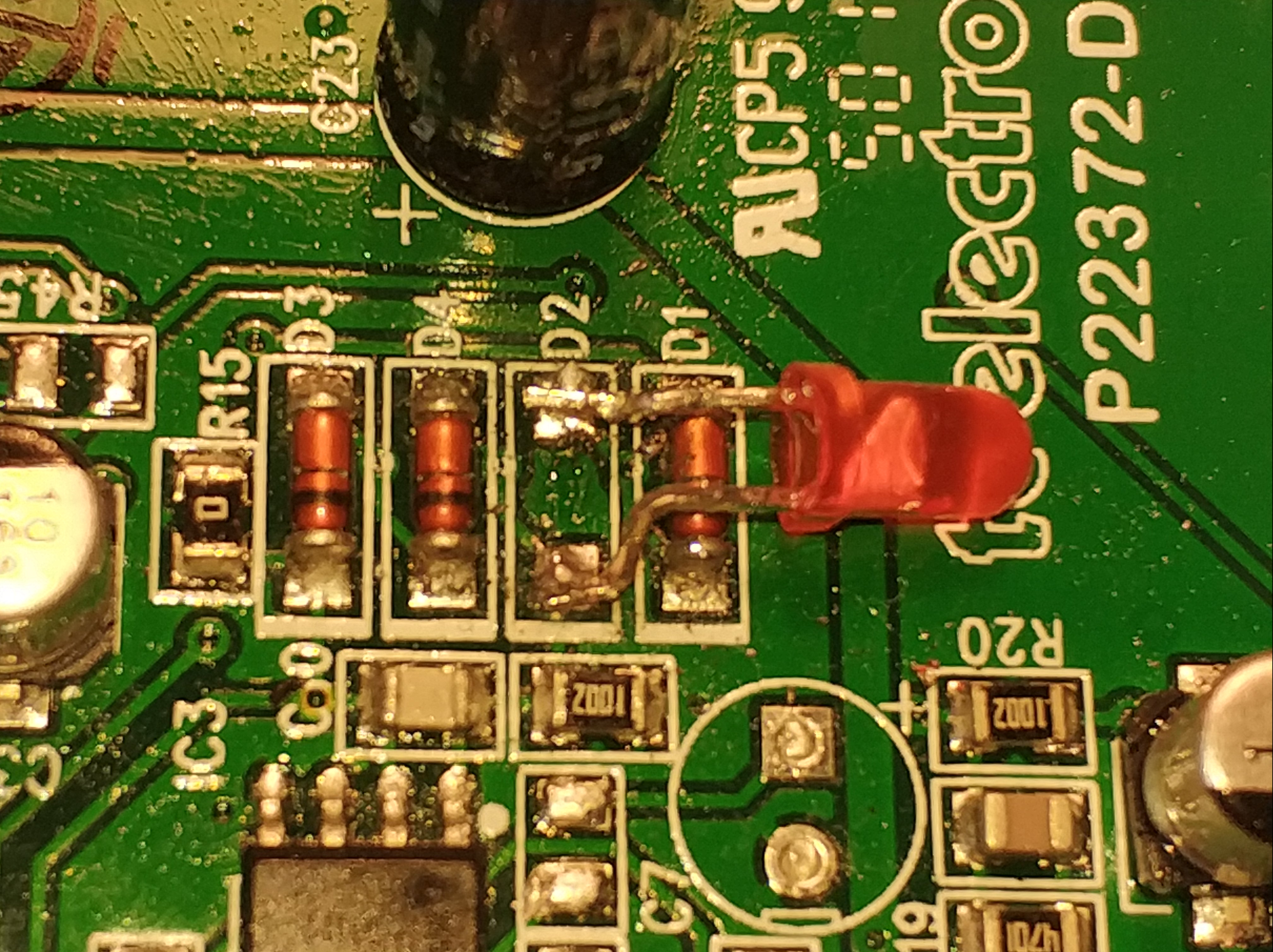
Now let’s decide about what to drop instead of the faulty diode. I didn’t want to replace any other components because of the lack of schematic and the intrinsic difficulty of replacing SMD components. Since I have experimented before with symmetrical clipping against asymmetrical clipping, it is not hard to guess that the replacing component had to be a different kind of diode. To make the clipping more open and asymmetrical at the same time, a LED was the perfect option. Common bipolar diodes have Vf = 0.6 V, while red LEDs have Vf = 1.2 V. Vf means forward voltage, that can be simplified as the minimum voltage that needs the diode to conduct a significant amount of current. That current is what makes clipping possible because the moment the audio signal reaches Vf, signal voltage starts to be limited. The higher the Vf for the clipping, the higher the signal can get before being clipped. In fact the clipping is not a all or nothing thing, but responds to a curve that is characteristic of each kind of diode.
In our original Mojomojo circuit, we had two diodes for the positive part of the signal and two diodes for the negative part. Total Voltage for clipping was 0.6 + 0.6 = 1.2 V. With a red LED replacing one of the four diodes, we will have 1.2 V in one direction and 0.6 + 1.2 = 1.8 V in the other. Why a red LED and not green, blue or yellow? Red ones have the lower Vf of all visible colors.

Red is a good choice for making it assymetrical and more open, but not too much. Sometimes, especially for mild overdrives, the total Vf is so high that you have no clipping at all. I think 1.2 V versus 1.8 V is a good balance.
The LED needs some shaping in order to be soldered on the surface of the board.


We have to be very careful and not let it contact any other component. As usual, but a little harder. Finally some hot glue to make it more resistant mecanically:

How does it sound? I didn’t have a recording of the original sound of my particular Mojomojo, and I think it is not very useful to upload a demo because the difference is subtle, to my ears it gives a little more mojo to the Mojomojo, or at least a different mojo. Some more high end and dynamics and less compression, given the higher Vf. Another LED colors can be tried, of course. Maybe I upload several demos of this and other mods in another post. But I don’t believe very much in online demos, they depend too much on the rest of the gear, and the player itself, of course.


