
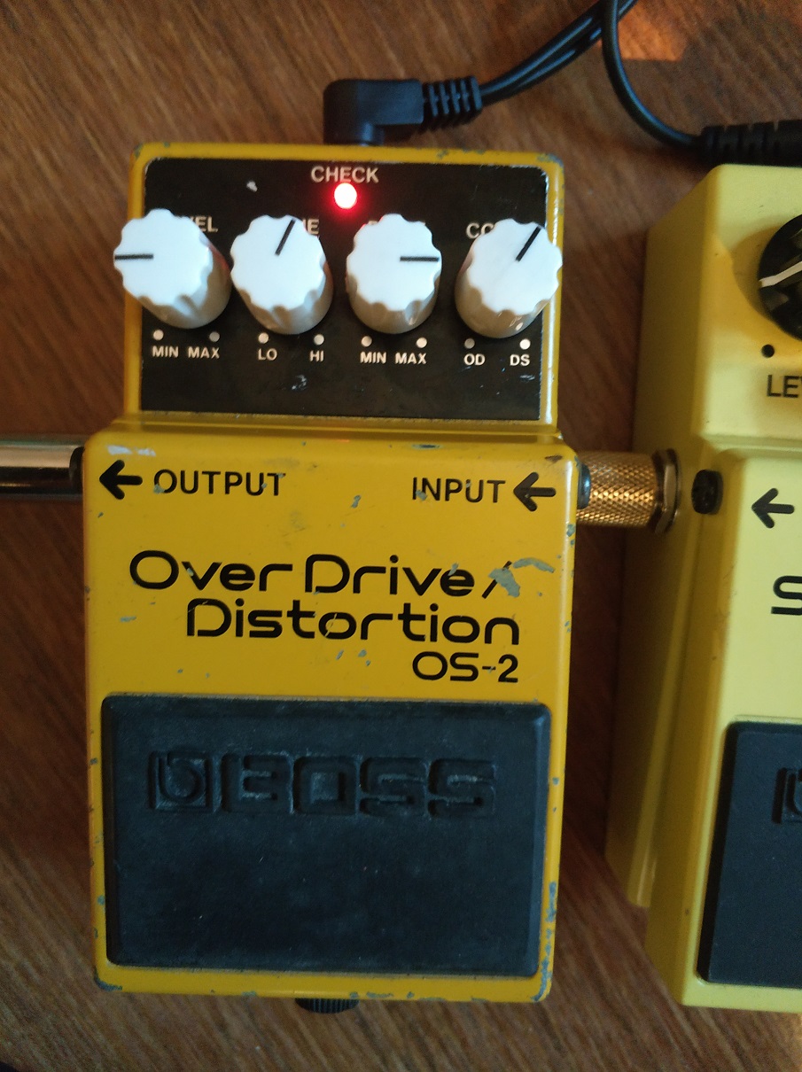
I have been playing for two weeks with a BOSS OS-2 overdrive/distortion pedal I found in ebay for repair. Repairing was easy, just needed some pots cleaning.

The concept is nice: there are two blended circuits:
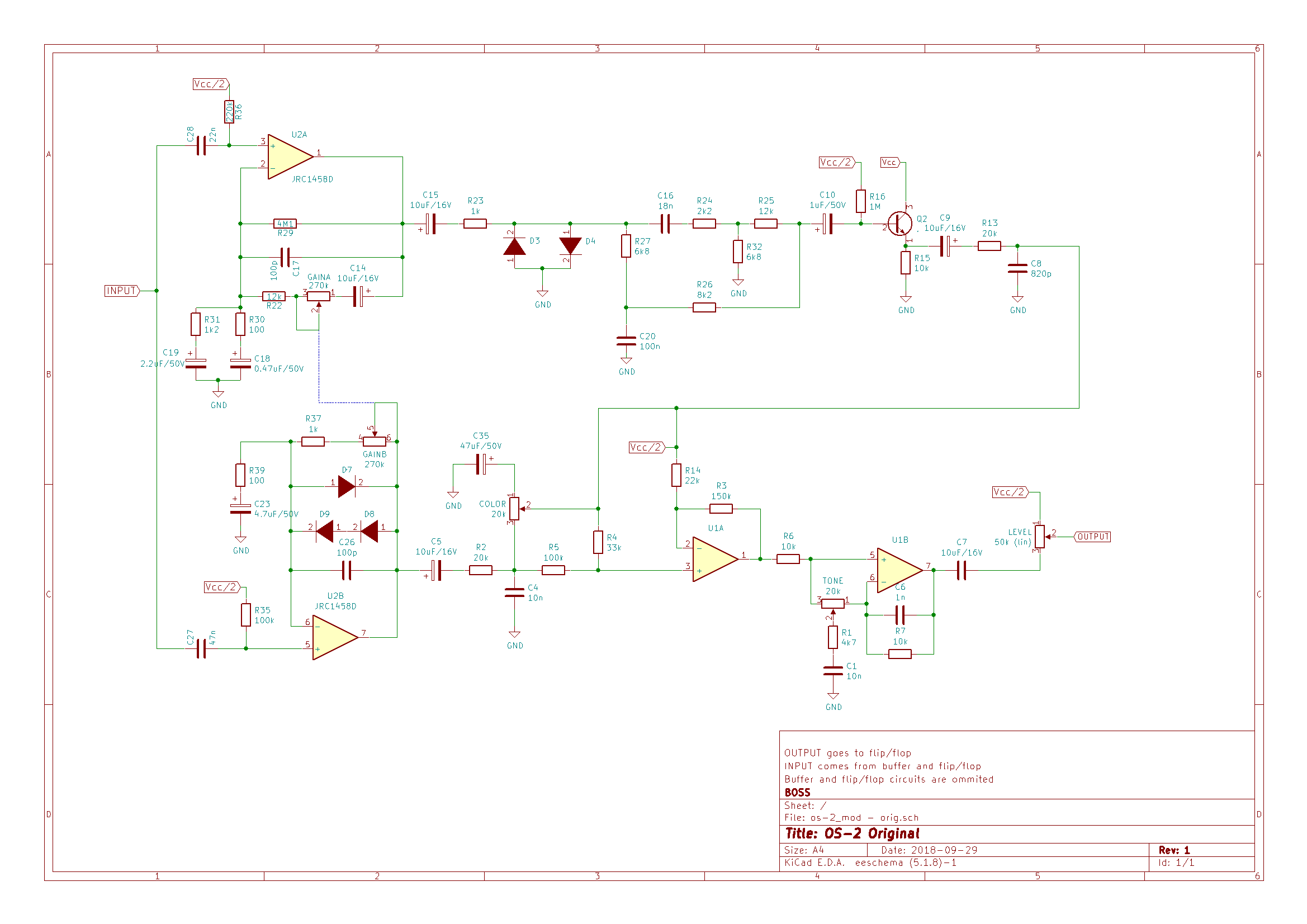
- Overdrive, by asymmetrical soft clipping in the feedback loop of an operational amplifier, like most overdrives out there.
- Distortion by symmetrical hard clipping in the output of the other operational amplifier of the same chip.
You can blend the two by rotating a “color” control, from overdrive on the left to distortion on the right. After the blend section, there is a tone one. The “Drive” pot is a dual 270k potentiometer, each unit connected to the feedback loop of each of the amplifier units.
Out of the brown box (it didn’t come with the original BOSS box) I found some things I didn’t like:
- Little bass response in the overdrive mode, too much treble for my liking. Usable for me, but could be improved (from my point of view, for my own needs).
- I usually don’t like pure distortions and hard clipping, so I didn’t expect to like this side too much. I found it too flat and hissing, with little mids, but having a nice boost in the 100Hz (aprox) freq.
I think there are almost no “bad designs” or “bad pedals” out there, it is just a matter of taste. Many like pedals that I hate (don’t want to give names). Maybe the best overdrive or distortion pedal is no pedal at all, but for people like me that usually don’t play on stadiums, distortion pedals are a good tool to get close to the tone of your favorite player.
Moreover, when you modify a pedal, you are not improving the design, but improving your particular unit for your particular taste. Most components vary a lot in value from unit to unit, and manufacturers have to take many constraints into consideration in their designs. Therefore I think we have to be humble when “improving” a device.
That said, in this case, I considered these objectives:
- Distortion side:
- Raising mids and cutting that hiss
- Trying asymmetrical clipping in this kind of circuits, just for fun
- Overdrive:
- Raising mids too, and add some more bass response
- Trying leds clipping for a supposedly more natural overdrive, and also for fun
After some tweaking and some regrets, I performed to the following changes:
| component | old value | new value | why |
| U2 (opamp) | JCR1458D | JCR4558D | JCR4558D has better characteristics: 1458D Input Resistance = 1M Slew Rate = 0,5V/uS4558: Input Resistance = 5M Slew Rate = 1V/uSSlew rate affects the circuit bandwidth higher limit, in this case from 8KHZ to 16KHz. Maybe it is overkill, but I think this gives more freedom at adjusting the frequency response of the circuit. |
| C6 | 1nF | 2n2F | Initially, I removed it but after Charles Willis suggestion, I replaced it for a 2.2nF capacitor. It should give more bass in the output of the tone stack. |
| C27 | 47nF | 220nF | Lowers freq. in high pass filter at the input of the overdrive section -> more bass |
| R39 | 100 | 150 | Lowers gain in overdrive. See C23 |
| C23 | 4.7uF | 2.2uF | In combination with R39, it forms a high pass filter, attenuating frequencies below the cut-off frequency. The modification changes the pass freq from 338Hz to 482Hz. In combination with the C27 change, it results in more mids |
| D7,D8,D9 | Junction diodes | D7,D8=Red LED – D9=BAT46 (Schottky) | It changes the form of the clipped signal. Red LEDs have Vf=1.8V (instead of 0,7) and different I/V curve. I put a schottky just to experiment, another kind of diode can be used, or just a cable for symmetrical clipping. Another LED would be too much Vf and can result in no clipping |
| R2 | 20K | 68K | This resistor is part of the circuit that balances overdrive and distortion. Since LEDs are used for clipping, the output voltage of the operational is too much when compared to distortion output. Raising the value of this resistor lowers the output of the overdrive section. R13 at the end of the distortion circuit can be lowered too, but that raises the cut-off frequency of the low pass filter formed by R13 and C8, not contributing to eliminate the hiss |
| C16 | 18nF | 22nF | Lowers the cut-off frequency of the high pass filter after the hard clipping section, raising mids in the overall circuit |
| D3,D4 | Junction diodes | D3=1N4148 – D4=BAT85 (Schottky) + 10 Ohms resistor | It changes the hard clipping section from symmetrical to asymmetrical. The schottky + resistor gives a smoother I/V curve than the diode alone. Just an experiment (successful for my ears), as in the soft clipping section |
| C8 | 820pF | 4.7nF | Lowers the cut-off frequency of the high pass filter after the hard clipping circuit. This is key to cut the hiss |

Lessons learned
At first I tried LEDs also in the hard clipping section, getting a not so nice result. Probing the circuit with the oscilloscope, I discovered that it was not clipping at all, you could remove the diodes and get the same output. Forward voltage is so high, even for red LEDs (different color LEDs have different Vf), that it didn’t clip at all. The distortion came from the saturated transistor and was not very pleasant.
Then I tried different combinations of Schottky and junction diodes (I like Schottky diodes lately…) until I got to the above blend.
I tried green and blue LEDs and combined LEDs with junction and Schottky in the soft clipping section, but I didn’t like the results. If you have read my other post about SD-1, green and schottky was my final combination in the BOSS SD-1, but it does not seem to work in the OS-2. The final combination was the nicer for my ears, just that.
I put a trimpot instead of R13, in order to adjust the output of the distortion circuit, but the result was catastrophic: more hiss and even oscillation when the trimpot got near zero ohms. So I changed R2, getting much better results.
As you can imagine, the values of the capacitors and resistance are not casual, I have tried many combinations and calculated some filter frequencies to get to those values. Some starting points came from forum posts and some other pages, and I changed some components and at the end returned to the original values (C26 for instance) . The lesson here is: calculate values for the filters involved and act with a purpose. I took some ideas from this post: https://www.roboticbeast.com/modification-de-la-boss-os-2/ but some didn’t wotk for me or with my unit. Another lesson (I already knew, of course) is that every modification affects the whole circuit in some measure, so you shouldn’t change a single component and see if you like it.
Also found a very useful tools for analyzing frequency responses by generating signals and capturing the output of the pedal with a computer and its sound card, more on this in some future post.
PD: if you make this mod, please comment below, I would like to keep track of people enjoying (or not) my mods.

[…] in frequency response between overdrive and distortion. I have tested my modified OS-2 (see BOSS OS-2 Overdrive/ Distortion MOD) with REW software and my laptop soundcard. It is very simple, you just have to connect the […]
LikeLike
[…] to be fixed. Their problem was the same, just the potentiometers need deep cleaning. I modified the OS-2, but after checking the OD-3 out, I didn’t feel like modifying it. Just started to love it: […]
LikeLike
I just got a OS-2. I really like it as it is, I dont wanna change too much I’d just like to get a bit thicker, fuller low end & some more bite from the lows in to the mids and from the lower mids to the lower treble frequencies and def gotta mello out that, I call it the Wide Overly Shrill maxed out classic boss pedal sound. Is there a few cap values and material types i could swap out in a select few places or should I just start trying out stuff? It sounds like you accomplished a few of the things I’d like to change. Do you have audio of the mods?? Please find me on FB or IG preferably if you can. I do most of my time there promoting a cable/harness builder and I wont miss any correspondence with you. I’d really like to hear your mods in action.
LikeLiked by 1 person
I don’t have an audio of the mod, let my try to record something these days and I’ll reach you with the results.
LikeLike
Removing C6 won’t give you more bass. C6 and R7 form a low pass filter that cuts out high frequency noise, mostly above human hearing at 15khz or so. Swap that 820pf cap for a 2.2nf and it should cut down the hiss a lot on the distortion side without dulling the high end very much at all.
LikeLike
Thanks, Charles, I’ll try what you say.
LikeLike
I tried your suggestion, not much difference but it sounds more round and with a little less hiss with distortion. I updated the article. Thanks again.
LikeLike
Is the dual 270k pot connected at pin 2 and 5? I’m not familiar with the dotted line on a schematic.
LikeLike
That is just a mechanical connection, sorry for the confusion. They are not electrically connected at all.
LikeLike
Greetings fellow DIYers. I have been working on a schematic I’ve been working on using a couple of other sources. I’m curious about an audio problem I’m having. What is C9 doing and if it were reversed, would it prevent audio from passing through? I assumed it was blocking DC voltage from passing.
LikeLike
You are right, C9 is blocking DC from passing, and its value has an impact on the range of frequencies that can pass through it, since it forms a high pass filter with R13. From my experience, If you reverse an electrolitic capacitor, it keeps on working but if the DC voltage is high you can burn it.
LikeLike
Did you trace the pedal to create the schematic? I’m still working on this one.
LikeLike
Do you know how accurate this schematic is? I and an associate are working on a trace and coming up with something a little different with the color pot, that’s why I’m curious.
LikeLike
Hi, Jimilee. I did not find the official schematic from BOSS, so I extracted it from some other non official schematics from forums and web sites. I did not include the switching part because that was not relevant for modifying the pedal. I did not trace the board, maybe I should have done it. What is different with the color pot?
LikeLike
With my limited tracing skills ,I’ve found vc/2 voltage on pin 2 of the color pot. Using this schematic, I had no audio until i used a 100k resister between pin 3 of u1a and vc/2. I found this on another schematic through searches. It works, but doesn’t sound the same as the original.
LikeLike
I have found 0 resistance between pin 2 and vcc/2 too, but cannot find any connectivity in the main board. Have you tried to connect pin 2 of color pot to vcc/2? Later if I have time, I’ll extract the auxiliary board, maybe there is the connection between pin 2 and vcc/2.
I am afraid that the original schematic someone traced long ago is wrong and everybody took it as the truth. Still cannot find a BOSS original schematic.
LikeLike
Hey, thanks for getting back to me, I appreciate it. I was pretty sure it was wrong, thanks for confirming that. I couldn’t find a boss schematic either. This thing is quite the enigma. Thanks for your help. If I come up with anything more, I’ll let you know. Let me know what you come up with if you have time, if you do t care to.
LikeLike
Hi, Jimilee. Tracing the auxiliary board (the one that connects the pots to the main board), I can see that pin 1 of level pot, that is connected to vcc/2, is also connected to pin 2 of color pot. So you were right, the original schematic is wrong and that color pin 2 is connected to vcc/2. I’ll change the schematic as soon as possible. Thanks a lot for your finding.
LikeLike
Absolutely. Thank you for your help.
LikeLike