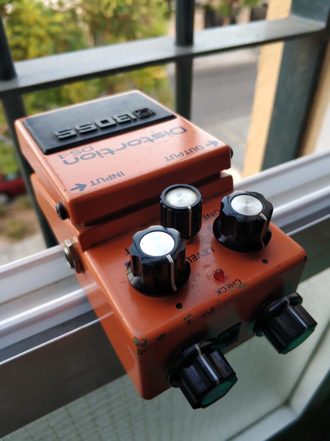
BOSS DS-1: modding my own mod

In my previous post https://electric-safari.com/2019/03/17/turn-a-boss-ds-1-into-a-nice-overdrive/ I converted the DS-1 distortion pedal into something very close to an overdrive. One of the things I changed was the clipping section; one of the diodes was replaced by a red led. I tried some other combinations, but not very scientifically, honestly. The final one was chosen by ear, and that’s the one I published. But the doubt about some other combinations remained in my head after that.

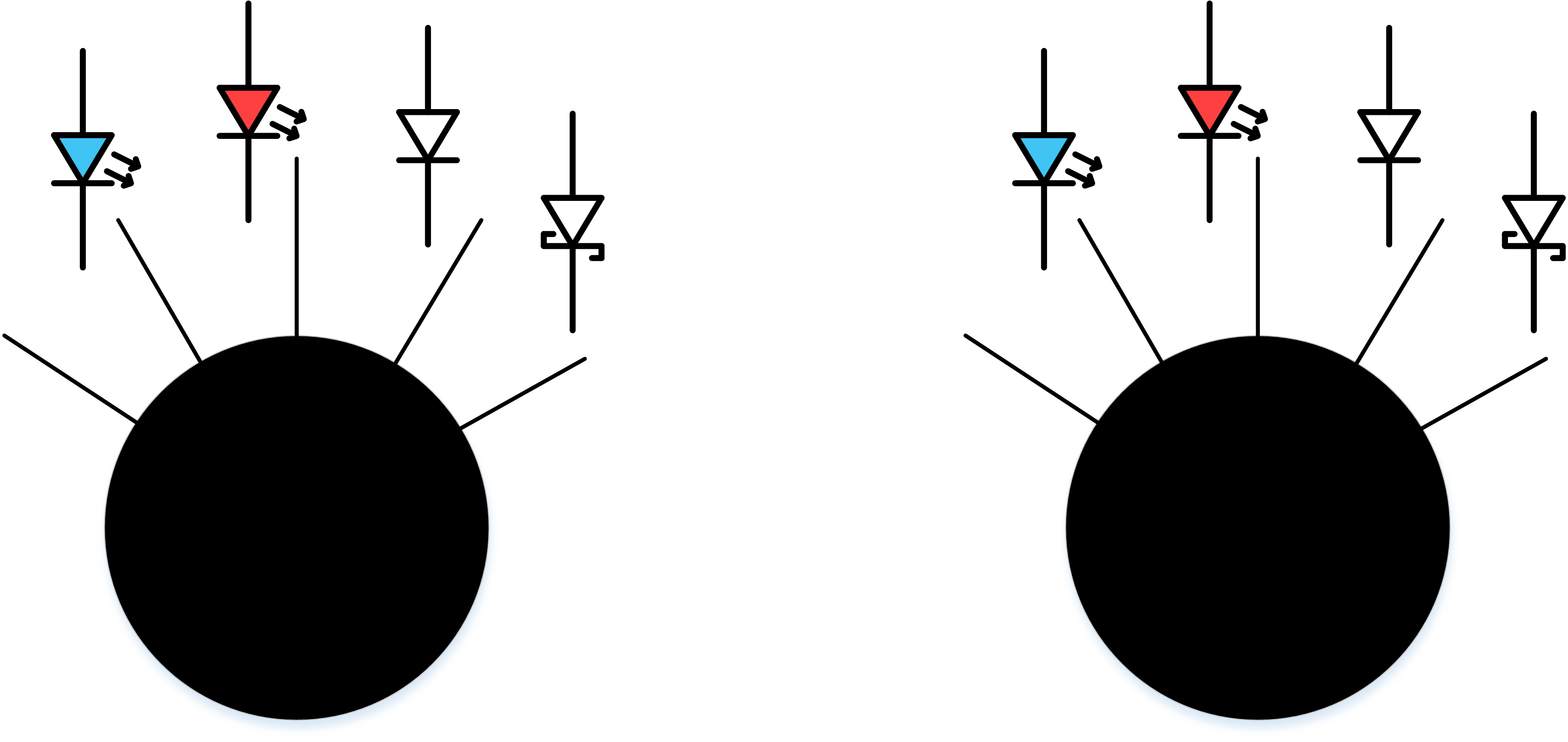
Recently I got another DS-1 in ebay, and after modifying it (following my own instructions), I decided to give it another twist: let the user decide what diode to use (or no diode at all) for each side of the clipping section. In the next diagram I show how I connected two rotary selectors for choosing the diodes:
The rotary selectors are these ones: https://es.aliexpress.com/item/32947552565.html?spm=a2g0s.9042311.0.0.6e1663c0haFbmP

The actual devices with the diodes connected:

The X and Y terminals from the diagram above have to be connected to one of the removed diodes terminals in the PCB (see the white and blue cables):

It is not necessary to connect anything to the other diode because the two diodes are connected cathode to anode and anode to cathode. Don’t connect one of the terminals to ground, as you could do with some other hard clipping designs (ProCo Rat, for instance) because that is not how they are connected in the DS-1.

The result:

The two selectors act (as I have connected them for my own convenience) as two “taps” for the two sides of the signal (positive and negative), as seen from the supply jack side of the pedal. Open the tap and you have a more open (less clipped) signal, close the tap and you have a more clipped signal. The sequence of clipping goes like this:

  • wide open, left position: no diode for clipping. The clipping comes from the transistor section and the operational
  • second position from the left: blue led, Vf=2V
  • third position from the left: red led, Vf=1.5V
  • fourth position from the left: original diode: Vf=0.5V
  • fifth position from the left: schottky diode: Vf=0.2V

Seen from the front, as you play, you can think about left=less volts / right=more volts.

You could say: there are repeated combinations, because for instance “red led + schottky = schottky + red led”, so I could have chosen a 15 positions (I think) rotary switch for all the valid combinations. Apart from the fact that a 15 positions switch is hard to find and it would have complicated the cabling, that hypothesis (“red led + schottky = schottky + red led”) is not completely true in the real world, because of two reasons:

  • Let’s face the truth: two different diodes with the same name do not have exactly the same Vf, not to mention the rest of the specs.
  • Clipping the positive part of the signal is not the same as clipping the negative part of the signal, because of the non linearities of the circuit design and components.

I think that setting two selectors is (as least for me) more intuitive. This is mostly an experiment that can be used also for gigging.

How does it sound

Yes, an experiment, but also a gigging pedal I am planning to use. In spite of the flexibility given by the two selectors, it doesn’t lose its original character. Selecting the combination: position 2 + position 3 (original diode + red led) it sound almost like the other DS-1 I modified, as expected, given the intrinsic differences of every unit components.

Selecting different positions for each selector, especially if they are very extreme, accentuates the asymmetrical character of the distortion (even harmonics, more on that here: https://blackstoneappliances.com/dist101.html)

The blue led combined with any other diode gives a very mid rangy character for my ear.

As you “open” the “tap”, the signal is louder. Selecting the open – open combination creates, as expected, a very loud but distorted signal, not bad given the fact that it is created by the transistor and the operational. Cannot be used as a clean boost pedal, but can crank a tube amp. 

At the other extreme, selecting the two schottky diodes and maxing the distortion control creates an almost fuzzy distortion. If you max the three pedal controls, select a neck humbucker pickup and lower the guitar tone control, the fuzz is there for you to enjoy. That way all the treble harmonics that you hear come from the pedal itself, not from the pickup.

Please let any thoughts in the comments section, and if you try this mod please let me know.

The DS-1 mod I mention above (Turn a BOSS DS-1 into a nice overdrive) has been implemented at least by two friends of mine (thanks Pepe and Juanjo for trying it out), and they are very happy users of it, I think they are even gigging with it. They call it “warrior mod” because of my last name in spanish.


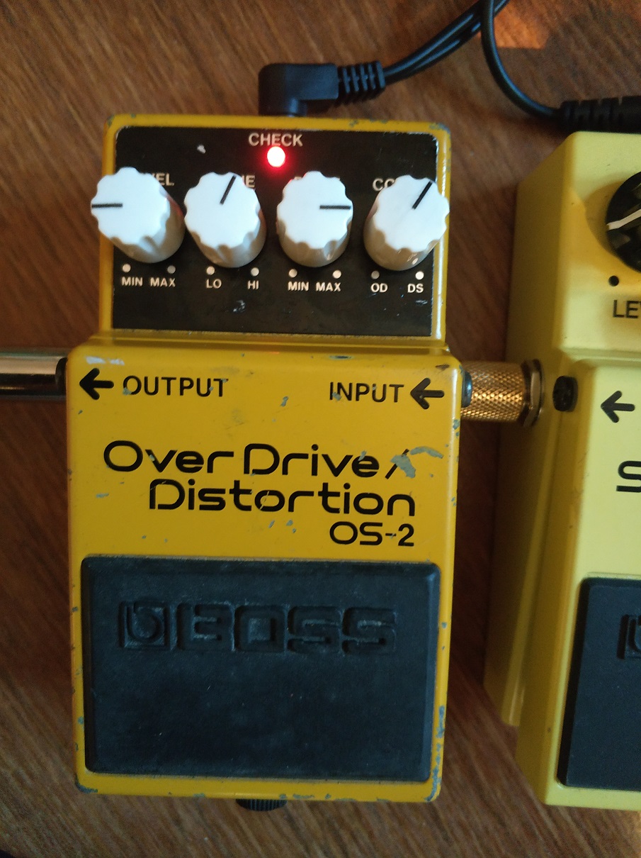
BOSS OS-2 Overdrive/ Distortion MOD

I have been playing for two weeks with a BOSS OS-2 overdrive/distortion pedal I found in ebay for repair. Repairing was easy, just needed some pots cleaning.

OS-2 with modified knobs and circuit

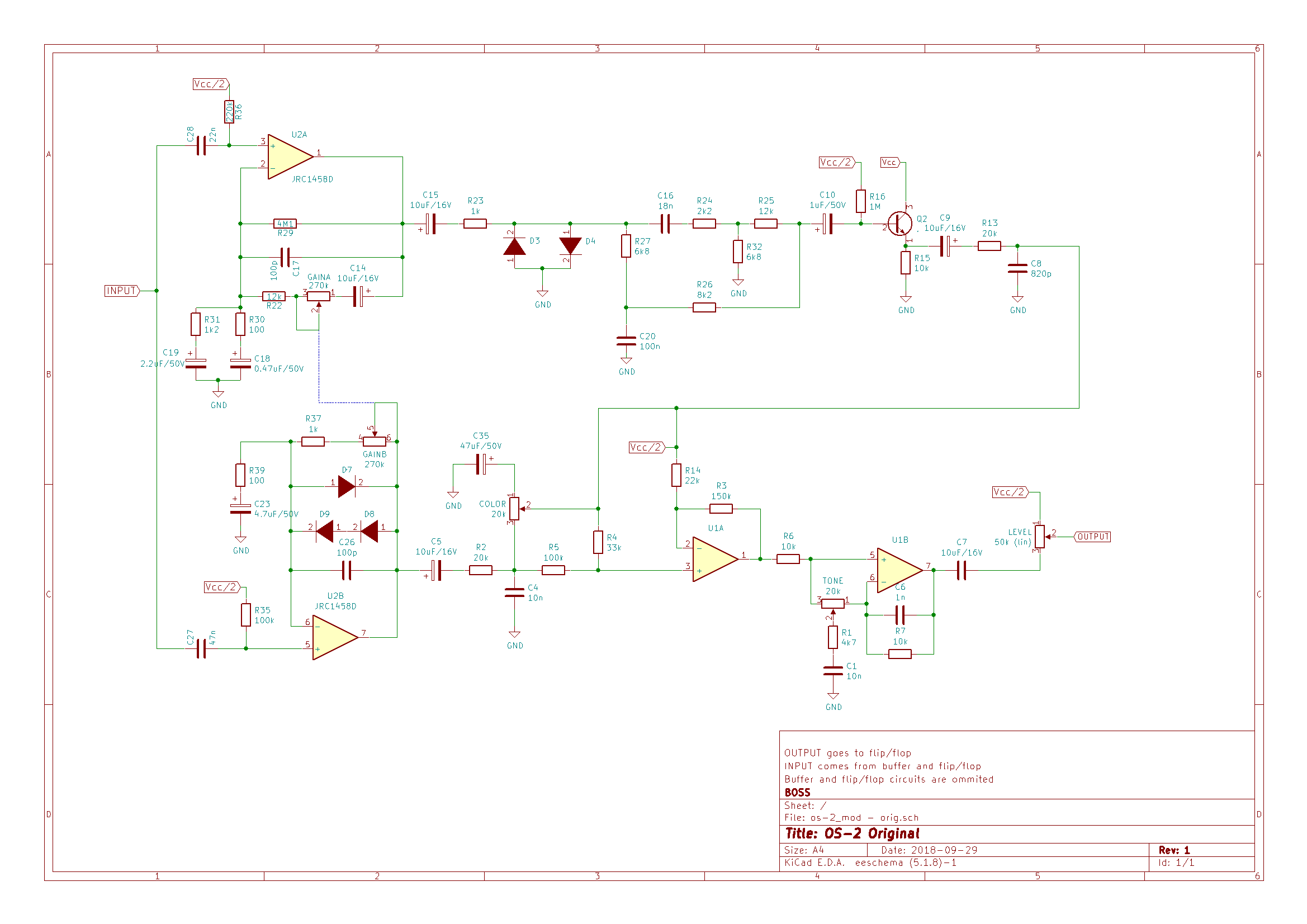
The concept is nice: there are two blended circuits:

  • Overdrive, by asymmetrical soft clipping in the feedback loop of an operational amplifier, like most overdrives out there.
  • Distortion by symmetrical hard clipping in the output of the other operational amplifier of the same chip.

You can blend the two by rotating a “color” control, from overdrive on the left to distortion on the right. After the blend section, there is a tone one. The “Drive” pot is a dual 270k potentiometer, each unit connected to the feedback loop of each of the amplifier units.

Out of the brown box (it didn’t come with the original BOSS box) I found some things I didn’t like:

  • Little bass response in the overdrive mode, too much treble for my liking. Usable for me, but could be improved (from my point of view, for my own needs).
  • I usually don’t like pure distortions and hard clipping, so I didn’t expect to like this side too much. I found it too flat and hissing, with little mids, but having a nice boost in the 100Hz (aprox) freq.
boss_os-2_orig
BOSS OS-2 Original circuit


I think there are almost no “bad designs” or “bad pedals” out there, it is just a matter of taste. Many like pedals that I hate (don’t want to give names). Maybe the best overdrive or distortion pedal is no pedal at all, but for people like me that usually don’t play on stadiums, distortion pedals are a good tool to get close to the tone of your favorite player.

Moreover, when you modify a pedal, you are not improving the design, but improving your particular unit for your particular taste. Most components vary a lot in value from unit to unit, and manufacturers have to take many constraints into consideration in their designs. Therefore I think we have to be humble when “improving” a device.

That said, in this case, I considered these objectives:

  • Distortion side:
    • Raising mids and cutting that hiss
    • Trying asymmetrical clipping in this kind of circuits, just for fun
  • Overdrive:
    • Raising mids too, and add some more bass response
    • Trying leds clipping for a supposedly more natural overdrive, and also for fun

After some tweaking and some regrets, I performed to the following changes:

component old value new value why
U2 (opamp) JCR1458D JCR4558D JCR4558D has better characteristics:
1458D
Input Resistance = 1M
Slew Rate = 0,5V/uS4558:
Input Resistance = 5M
Slew Rate = 1V/uSSlew rate affects the circuit bandwidth higher limit, in this case from 8KHZ to 16KHz. Maybe it is overkill, but I think this gives more freedom at adjusting the frequency response of the circuit.
C6 1nF 2n2F Initially, I removed it but after Charles Willis suggestion, I replaced it for a 2.2nF capacitor. It should give more bass in the output of the tone stack.
C27 47nF 220nF Lowers freq. in high pass filter at the input of the overdrive section -> more bass
R39 100 150 Lowers gain in overdrive. See C23
C23 4.7uF 2.2uF In combination with R39, it forms a high pass filter, attenuating frequencies below the cut-off frequency. The modification changes the pass freq from 338Hz to 482Hz. In combination with the C27 change, it results in more mids
D7,D8,D9 Junction diodes D7,D8=Red LED – D9=BAT46 (Schottky) It changes the form of the clipped signal. Red LEDs have Vf=1.8V (instead of 0,7) and different I/V curve. I put a schottky just to experiment, another kind of diode can be used, or just a cable for symmetrical clipping. Another LED would be too much Vf and can result in no clipping
R2 20K 68K This resistor is part of the circuit that balances overdrive and distortion. Since LEDs are used for clipping, the output voltage of the operational is too much when compared to distortion output. Raising the value of this resistor lowers the output of the overdrive section. R13 at the end of the distortion circuit can be lowered too, but that raises the cut-off frequency of the low pass filter formed by R13 and C8, not contributing to eliminate the hiss
C16 18nF 22nF Lowers the cut-off frequency of the high pass filter after the hard clipping section, raising mids in the overall circuit
D3,D4 Junction diodes D3=1N4148 – D4=BAT85 (Schottky) + 10 Ohms resistor It changes the hard clipping section from symmetrical to asymmetrical. The schottky + resistor gives a smoother I/V curve than the diode alone. Just an experiment (successful for my ears), as in the soft clipping section
C8 820pF 4.7nF Lowers the cut-off frequency of the high pass filter after the hard clipping circuit. This is key to cut the hiss
boss_os-2_mod
BOSS OS-2 Modified circuit


Lessons learned

At first I tried LEDs also in the hard clipping section, getting a not so nice result. Probing the circuit with the oscilloscope, I discovered that it was not clipping at all, you could remove the diodes and get the same output. Forward voltage is so high, even for red LEDs (different color LEDs have different Vf), that it didn’t clip at all. The distortion came from the saturated transistor and was not very pleasant.

Then I tried different combinations of Schottky and junction diodes (I like Schottky diodes lately…) until I got to the above blend.

I tried green and blue LEDs and combined LEDs with junction and Schottky in the soft clipping section, but I didn’t like the results. If you have read my other post about SD-1, green and schottky was my final combination in the BOSS SD-1, but it does not seem to work in the OS-2. The final combination was the nicer for my ears, just that.

I put a trimpot instead of R13, in order to adjust the output of the distortion circuit, but the result was catastrophic: more hiss and even oscillation when the trimpot got near zero ohms. So I changed R2, getting much better results.

As you can imagine, the values of the capacitors and resistance are not casual, I have tried many combinations and calculated some filter frequencies to get to those values. Some starting points came from forum posts and some other pages, and I changed some components and at the end returned to the original values (C26 for instance) . The lesson here is: calculate values for the filters involved and act with a purpose. I took some ideas from this post: https://www.roboticbeast.com/modification-de-la-boss-os-2/ but some didn’t wotk for me or with my unit. Another lesson (I already knew, of course) is that every modification affects the whole circuit in some measure, so you shouldn’t change a single component and see if you like it.

Also found a very useful tools for analyzing frequency responses by generating signals and capturing the output of the pedal with a computer and its sound card, more on this in some future post.

PD: if you make this mod, please comment below, I would like to keep track of people enjoying (or not) my mods.

BOSS SD-1 SUPER Overdrive MOD

Out of curiosity, I bought a second hand SD-1, just to try it as is, and try some of the mods people have been doing to this pedal for the last decades. Some mods try to transform it into a TS9 or even a TS808, so you can turn this relatively cheap pedal into a more expensive one. But this box has its own personality, tsd-1he design is very similar to TS9 but with some remarkable differences:
  • Clipping is asymmetrical, two diodes forward and one backwards (in the direction of the operational). Asymmetrical clipping sounds different than symmetrical one, some people describe it as harsh or hairy of fuzzy compared to the latter.
  • There is no capacitor in the feedback loop of the clipping amplifier. This capacitor smooths the clipping a little, giving the TubeScreamer part of its particular tone.
  • Tone control is very similar but with different component values and with a capacitor (C6) in the feedback loop of the tone control operational amplifier. This capacitor is the first thing I have seen every mod removes because it sucks a significant amount of bass frequencies to the signal.

After trying the pedal for a while, I quickly noticed what most people complain about, this makes the guitar sound thinner. This has not to be bad in every ocasion, especially in live gigs situations where you want to sound in a different spectrum space than the rest of the instruments. But ok, I want more bass too. In this clip I recorded the original sound of the pedal, playing with a RS420 (humbuckers) and a Fender Blues Deluxe amp (please don’t pay attention to the music, just the sound 😉 ):

To correct this defect or feature, there are multiple mods out there, usually people remove capacitor C6 and change values of R6 and C3, which connect the feedback loop and the negative operational input to a voltage divider, in a similar way to he TS9 connects those to ground. lowering R6 and raising C3 values results in more bass response from the clipping circuit. See below the schematic:

boss-sd1-super-overdrive
BOSS SD1

I chose to make this changes in order to get a nice tone from the pedal:

  • C6: instead of removing, changed it with a 100pF capacitor from its original value of 10nF.
  • C3: raised from 47nF to 100nF.
  • R6: lowered to 3K3

The other section where people make changes is the clipping circuit. Many mods aim in the direction of getting symmetrical clipping, but I didn’t want another TubeScreamer. Instead of that, I wanted to enhance the personality of the effect by exaggerating the asymmetry of the clipping section. Asymmetry comes from using a different quantity of diodes in each direction, or from using diodes with different specifications, especially with different forward voltages (Vf). Vf is different for the following types of diodes:

  • Ge diodes: low Vf, around 0,3V
  • Si diodes: usually around 0,6V
  • LED diodes: depends on the color, 2V for green ones, 1,6 for red ones.

So using a Ge diode in one sense and a LED in the other, we get asymmetrical clipping, right? Right, but Ge diodes are expensive, hard to find and unstable. I read about simulating Ge diodes with schottky diodes in this article:

http://rezzonics.blogspot.com/2014/01/germanium-diodes-vs-schottky-diodes-for.html

Ge diodes are used in some mods also because of the smooth I-V curve the exhibit. Schottky diodes have a low Vf too, but the I-V curve is more abrupt than the Ge one. By adding a resistor in series, you can get a similar response, at a lower cost and with more stability.

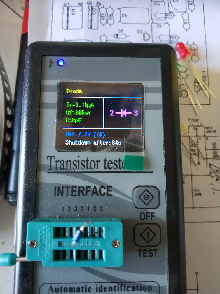
In my mod, I have replaced D5 and D6 (in series in the original circuit) with a resistor (10 Ohms) and a schottky diode (BAT46) with a Vf of 365mV. And D4 has been replaced with a green LED with VF=2V. You can see the measures below:

BAT46green_diode

The components used:

componentes

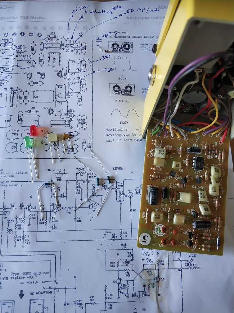
And the changes to make:

PCB-antes

For the clipping section, that I suppose will be subject of further modifications, I have replaced the original components with sockets. In the picture below you can see the other components replaced too:

sockets

Here you can see a detail of the changes in the clipping section:

detalle_clipping

And the result in the following record. I was not trying to play a song, just to get all the possible tones from the pedal. Please forgive me if I get sloppy:

I can perceive these differences after playing for a while:

  • More volume at the same “level”.
  • Much more bass frequencies, without being too much for a band situation, I think (has to be tested in a band situation).
  • More of the asymmetrical character: “harsher” when playing harder, keeping dynamics (I think more than the original, maybe I am somewhat subjective).
  • I think the sound changes more than the original when moving the drive control: from a smooth, almost TS9-esque overdrive at low gain levels to almost fuzzy and even octave-like at maximum gain.

If you are interested in this mod, please try it, test it and give me your opinion in the comments section. If you improve it, tell me how. If you like it, give me a “like”, and if it’s possible for you, mention my blog to yout friends 🙂 Mods have no copyright, but we like some recognition, don’t we?


Edited on March 16 2019:

Some days ago I put a red led instead of the green one. Now the overdrive is more usable and versatile, although the octave effect is less pronunciated.

PD (May 2 2022): 

A more simple modification that makes the pedal even more usable is just changing  D4 for a red led and leaving the other diodes as they are. I did this for a friend that wanted a less edgy sound, and the result is better than my original mod.

PD: si hacéis ese mod, ponedlo en los comentarios abajo. Me gustaría saber si la gente disfruta (o no) de mis mods.