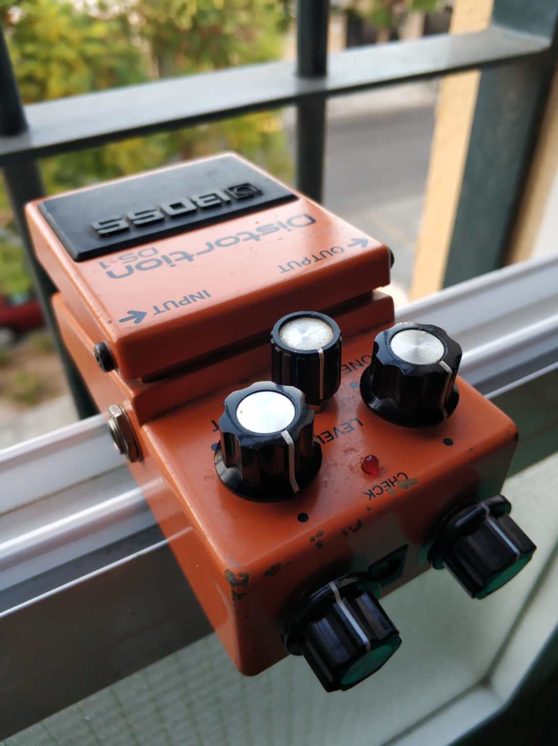
BOSS DS-1: modding my own mod

In my previous post https://electric-safari.com/2019/03/17/turn-a-boss-ds-1-into-a-nice-overdrive/ I converted the DS-1 distortion pedal into something very close to an overdrive. One of the things I changed was the clipping section; one of the diodes was replaced by a red led. I tried some other combinations, but not very scientifically, honestly. The final one was chosen by ear, and that’s the one I published. But the doubt about some other combinations remained in my head after that.

Recently I got another DS-1 in ebay, and after modifying it (following my own instructions), I decided to give it another twist: let the user decide what diode to use (or no diode at all) for each side of the clipping section. In the next diagram I show how I connected two rotary selectors for choosing the diodes:
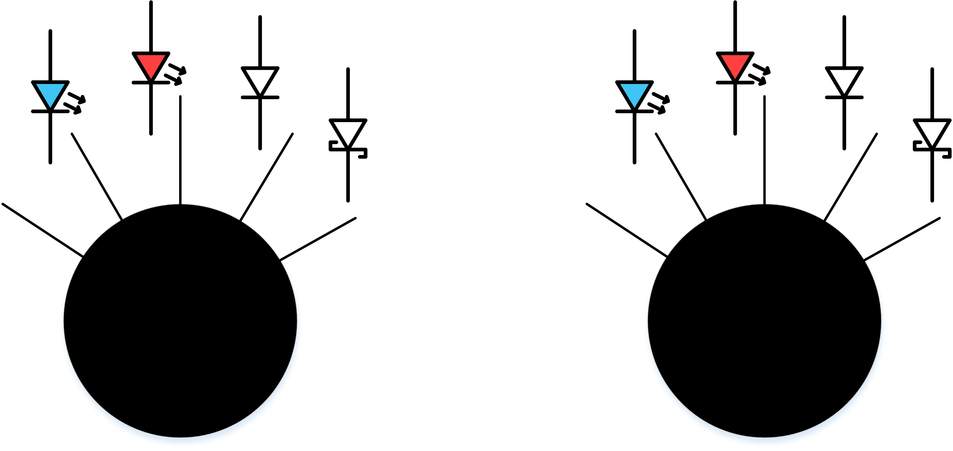
The rotary selectors are these ones: https://es.aliexpress.com/item/32947552565.html?spm=a2g0s.9042311.0.0.6e1663c0haFbmP

The actual devices with the diodes connected:

The X and Y terminals from the diagram above have to be connected to one of the removed diodes terminals in the PCB (see the white and blue cables):

It is not necessary to connect anything to the other diode because the two diodes are connected cathode to anode and anode to cathode. Don’t connect one of the terminals to ground, as you could do with some other hard clipping designs (ProCo Rat, for instance) because that is not how they are connected in the DS-1.

The result:

The two selectors act (as I have connected them for my own convenience) as two “taps” for the two sides of the signal (positive and negative), as seen from the supply jack side of the pedal. Open the tap and you have a more open (less clipped) signal, close the tap and you have a more clipped signal. The sequence of clipping goes like this:

  • wide open, left position: no diode for clipping. The clipping comes from the transistor section and the operational
  • second position from the left: blue led, Vf=2V
  • third position from the left: red led, Vf=1.5V
  • fourth position from the left: original diode: Vf=0.5V
  • fifth position from the left: schottky diode: Vf=0.2V

Seen from the front, as you play, you can think about left=less volts / right=more volts.

You could say: there are repeated combinations, because for instance “red led + schottky = schottky + red led”, so I could have chosen a 15 positions (I think) rotary switch for all the valid combinations. Apart from the fact that a 15 positions switch is hard to find and it would have complicated the cabling, that hypothesis (“red led + schottky = schottky + red led”) is not completely true in the real world, because of two reasons:

  • Let’s face the truth: two different diodes with the same name do not have exactly the same Vf, not to mention the rest of the specs.
  • Clipping the positive part of the signal is not the same as clipping the negative part of the signal, because of the non linearities of the circuit design and components.

I think that setting two selectors is (as least for me) more intuitive. This is mostly an experiment that can be used also for gigging.

How does it sound

Yes, an experiment, but also a gigging pedal I am planning to use. In spite of the flexibility given by the two selectors, it doesn’t lose its original character. Selecting the combination: position 2 + position 3 (original diode + red led) it sound almost like the other DS-1 I modified, as expected, given the intrinsic differences of every unit components.

Selecting different positions for each selector, especially if they are very extreme, accentuates the asymmetrical character of the distortion (even harmonics, more on that here: https://blackstoneappliances.com/dist101.html)

The blue led combined with any other diode gives a very mid rangy character for my ear.

As you “open” the “tap”, the signal is louder. Selecting the open – open combination creates, as expected, a very loud but distorted signal, not bad given the fact that it is created by the transistor and the operational. Cannot be used as a clean boost pedal, but can crank a tube amp. 

At the other extreme, selecting the two schottky diodes and maxing the distortion control creates an almost fuzzy distortion. If you max the three pedal controls, select a neck humbucker pickup and lower the guitar tone control, the fuzz is there for you to enjoy. That way all the treble harmonics that you hear come from the pedal itself, not from the pickup.

Please let any thoughts in the comments section, and if you try this mod please let me know.

The DS-1 mod I mention above (Turn a BOSS DS-1 into a nice overdrive) has been implemented at least by two friends of mine (thanks Pepe and Juanjo for trying it out), and they are very happy users of it, I think they are even gigging with it. They call it “warrior mod” because of my last name in spanish.


Asymmetrical Octaver Effect

In a previous post, I told how I made an EQD Tentacle Clon in a 1590 Enclosure. I took the layout from http://tagboardeffects.blogspot.com.es/2016/11/earthquaker-devices-tentacle.html and made some minor changes:

  • I used NPN transistors with a high beta (>400), I think they will give higher input gain and more output gain in the final stage.
  • I had a very anoying noise in this circuit from a cheap power supply. Added a 56 Ohms resistor between supply 9V and circuit and the noise disappeared completely. It seems that the 100uF capacitor was not enough and needed a little resistor to absorb the noise.
  • Ommited the two bottom rows with no function.

Yesterday a made a new, more drastical change: I swapped one of the two rectifier diodes (1N4148, Vf = 0.7V) with a BAT46 Schottky diode, with Vf = 0.3V, just to experiment with this component.

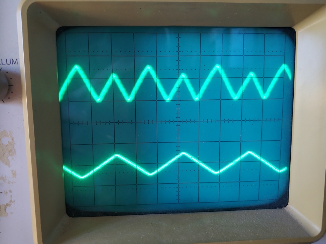
The electrical result is an asymmetrical rectification of the input signal, as can be seen in the oscilloscope:

IMG_20181004_134811
input signal below, output signal above

The audible result is a more natural sounding octave effect. Usually octavers have to be combined with overdrives or fuzzes in order to be bearable. Otherwise they sound too robotic and are unusable, at least for me. With this change, even if visually does not seem to be very different from its symmetrical counterpart, at least for my ears it sounds like a very dynamic distortion, and of course gets improved with some kind of light distortion after it.

BOSS SD-1 SUPER Overdrive MOD

Out of curiosity, I bought a second hand SD-1, just to try it as is, and try some of the mods people have been doing to this pedal for the last decades. Some mods try to transform it into a TS9 or even a TS808, so you can turn this relatively cheap pedal into a more expensive one. But this box has its own personality, tsd-1he design is very similar to TS9 but with some remarkable differences:
  • Clipping is asymmetrical, two diodes forward and one backwards (in the direction of the operational). Asymmetrical clipping sounds different than symmetrical one, some people describe it as harsh or hairy of fuzzy compared to the latter.
  • There is no capacitor in the feedback loop of the clipping amplifier. This capacitor smooths the clipping a little, giving the TubeScreamer part of its particular tone.
  • Tone control is very similar but with different component values and with a capacitor (C6) in the feedback loop of the tone control operational amplifier. This capacitor is the first thing I have seen every mod removes because it sucks a significant amount of bass frequencies to the signal.

After trying the pedal for a while, I quickly noticed what most people complain about, this makes the guitar sound thinner. This has not to be bad in every ocasion, especially in live gigs situations where you want to sound in a different spectrum space than the rest of the instruments. But ok, I want more bass too. In this clip I recorded the original sound of the pedal, playing with a RS420 (humbuckers) and a Fender Blues Deluxe amp (please don’t pay attention to the music, just the sound 😉 ):

To correct this defect or feature, there are multiple mods out there, usually people remove capacitor C6 and change values of R6 and C3, which connect the feedback loop and the negative operational input to a voltage divider, in a similar way to he TS9 connects those to ground. lowering R6 and raising C3 values results in more bass response from the clipping circuit. See below the schematic:

boss-sd1-super-overdrive
BOSS SD1

I chose to make this changes in order to get a nice tone from the pedal:

  • C6: instead of removing, changed it with a 100pF capacitor from its original value of 10nF.
  • C3: raised from 47nF to 100nF.
  • R6: lowered to 3K3

The other section where people make changes is the clipping circuit. Many mods aim in the direction of getting symmetrical clipping, but I didn’t want another TubeScreamer. Instead of that, I wanted to enhance the personality of the effect by exaggerating the asymmetry of the clipping section. Asymmetry comes from using a different quantity of diodes in each direction, or from using diodes with different specifications, especially with different forward voltages (Vf). Vf is different for the following types of diodes:

  • Ge diodes: low Vf, around 0,3V
  • Si diodes: usually around 0,6V
  • LED diodes: depends on the color, 2V for green ones, 1,6 for red ones.

So using a Ge diode in one sense and a LED in the other, we get asymmetrical clipping, right? Right, but Ge diodes are expensive, hard to find and unstable. I read about simulating Ge diodes with schottky diodes in this article:

http://rezzonics.blogspot.com/2014/01/germanium-diodes-vs-schottky-diodes-for.html

Ge diodes are used in some mods also because of the smooth I-V curve the exhibit. Schottky diodes have a low Vf too, but the I-V curve is more abrupt than the Ge one. By adding a resistor in series, you can get a similar response, at a lower cost and with more stability.

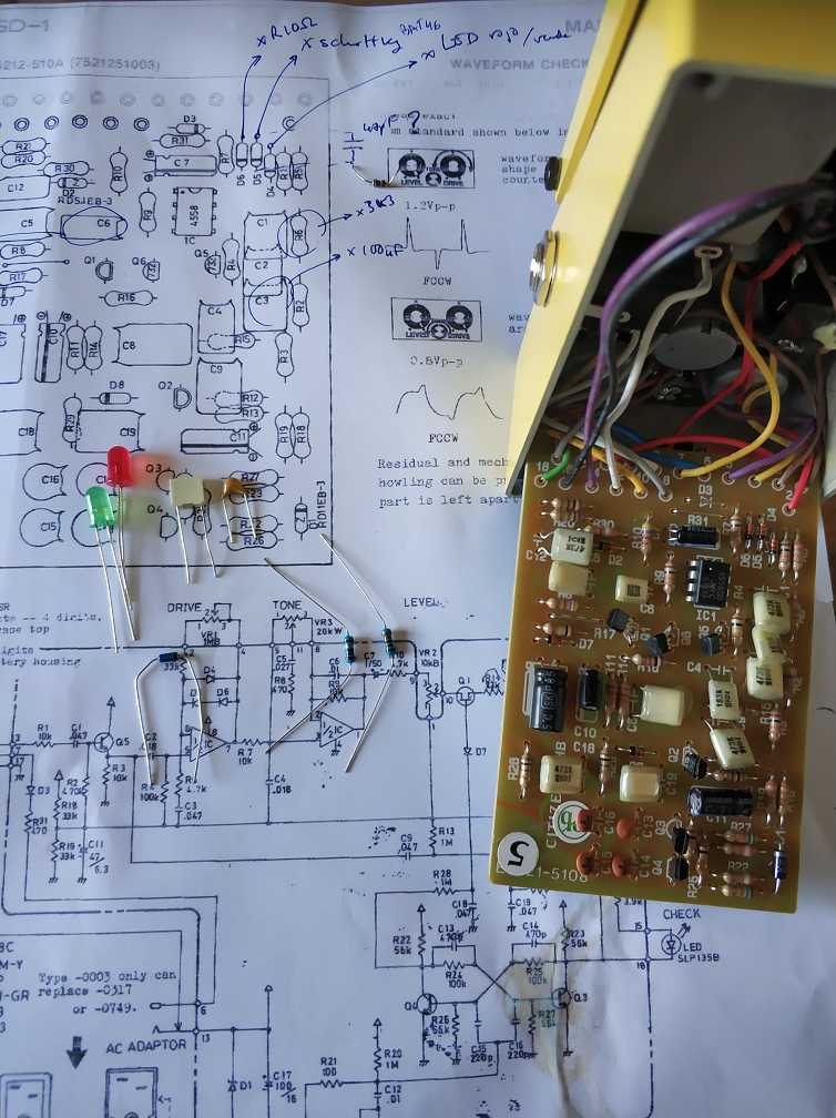
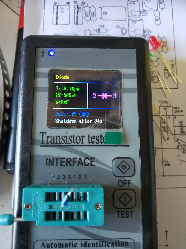
In my mod, I have replaced D5 and D6 (in series in the original circuit) with a resistor (10 Ohms) and a schottky diode (BAT46) with a Vf of 365mV. And D4 has been replaced with a green LED with VF=2V. You can see the measures below:

BAT46green_diode

The components used:

componentes

And the changes to make:

PCB-antes

For the clipping section, that I suppose will be subject of further modifications, I have replaced the original components with sockets. In the picture below you can see the other components replaced too:

sockets

Here you can see a detail of the changes in the clipping section:

detalle_clipping

And the result in the following record. I was not trying to play a song, just to get all the possible tones from the pedal. Please forgive me if I get sloppy:

I can perceive these differences after playing for a while:

  • More volume at the same “level”.
  • Much more bass frequencies, without being too much for a band situation, I think (has to be tested in a band situation).
  • More of the asymmetrical character: “harsher” when playing harder, keeping dynamics (I think more than the original, maybe I am somewhat subjective).
  • I think the sound changes more than the original when moving the drive control: from a smooth, almost TS9-esque overdrive at low gain levels to almost fuzzy and even octave-like at maximum gain.

If you are interested in this mod, please try it, test it and give me your opinion in the comments section. If you improve it, tell me how. If you like it, give me a “like”, and if it’s possible for you, mention my blog to yout friends 🙂 Mods have no copyright, but we like some recognition, don’t we?


Edited on March 16 2019:

Some days ago I put a red led instead of the green one. Now the overdrive is more usable and versatile, although the octave effect is less pronunciated.

PD (May 2 2022): 

A more simple modification that makes the pedal even more usable is just changing  D4 for a red led and leaving the other diodes as they are. I did this for a friend that wanted a less edgy sound, and the result is better than my original mod.

PD: si hacéis ese mod, ponedlo en los comentarios abajo. Me gustaría saber si la gente disfruta (o no) de mis mods.