BOSS OD-3 and J.Rockett Tim Pierce Overdrive

Recently I acquired a BOSS OD-3 Overdrive by chance, just because it was being sold by the same vendor than the BOSS OS-2, both to be fixed. Their problem was the same, just the potentiometers needed deep cleaning. I modified the OS-2, but after checking the OD-3 out, I didn’t feel like modifying it. Just started to love it: very natural sounding, following dynamics while playing, the most amp-like overdrive I have had in my hands.

I have played for a while with it and with my other favorite overdrive, the J.Rockett Tim Pierce Overdrive. This is an overdrive based on the typical operational feedback loop soft clipping (like TubeScreamer), very well designed and manufactured, with an additional, very useful and sweet boost. It cleans up very well when playing soft and have the distortion range I need. And because of it I have become a fan of a superguitar player, Tim Pierce.

Both overdrives are amazing, but sound differently, each one is good for each style and situation, and when stacked, you get a very mid rangey, cutting through tone, while not too dirty tone. I feel the OD-3 more dynamic, with more bass response, while the Tim Pierce is more focused on mids and covers a wider distortion range.

The circuits are very different. I don’t have schematics for Tim Pierce, but seems very similar to J. Rockett Animal Overdrive plus the boost circuit they call “Power Amp”, because  it is designed to emulate one of Tim Pierce’s favorite amps, the Naylor SD60. Basically it is a Tubescreamer style overdrive with four diodes placed in pairs in the feedback loop of a JRC4558 opamp, and very well chosen values for the different resistors and capacitors to tailor the frequency response. BOSS OD-3, on the other hand, has a very original design I am still trying to understand, based on a two stage diodes clipping with JRC4558 JFET transistors. There is an operational amplifier, used only for tone shaping and signal level raising. You can see below the schematics:

BOSS OD-3
BOSS OD-3

Trying to dig into the differences between the two styles of clipping, I did some measurements with my laptop. First I generated a couple of signals and captured the output with a Oscilloscope software, let’s see the results.

Pedal settings

These are the settings of both pedals for the measurements, they are basically my favorite settings:

IMG_20181013_121744
BOSS OD-3 and Tim Pierce settings

Time domain

First, let’s see how they react in front of a triangle signal, probably the most simple signal with some harmonics. I have used my soundcard and a great tool called “Soundcard Oscilloscope“. Frequency is 440Hz and level is 100mV, green line is the original signal and red line is the distorted one, for all graphs:

BOSS OD-3 - 440 Hz triangle, 100mV
BOSS OD-3 – 440 Hz triangle, 100mV
Tim Pierce - 440 Hz triangle, 100mV
Tim Pierce – 440 Hz triangle, 100mV

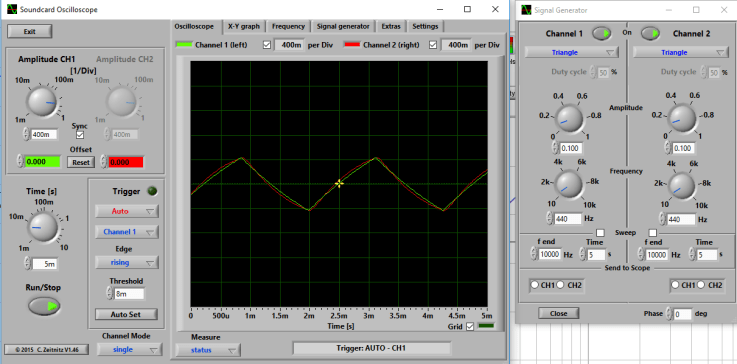
Interestingly, the Tim Pierce seems to almost not distort the signal, while the OD-3 produces a nice gradual clipping of the signal. Working with smaller signals and different frequencies, both seem to be distorting signals as little as 5mV, keeping almost this same shapes. To explain why they seem cleaner to the ear for smaller signals, a more extensive study should be done, with many frequencies and levels and a real or simulated guitar signal.

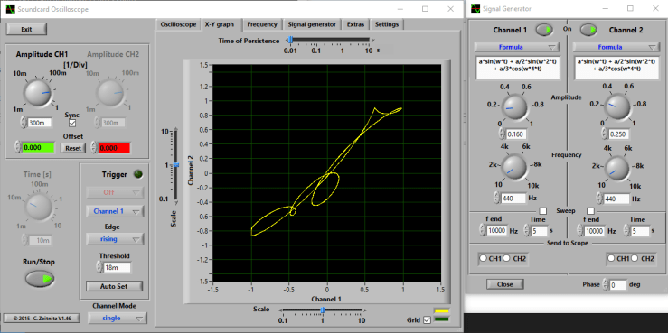
For this article, I have used a formula that yields a signal with some harmonics, trying to mimic what a guitar output signal could seem like: a*sin(w*t) + a/2sin(w*2*t) + a/3*cos(w*4*t). It is not by any means a guitar signal emulation, just something a little more complex than a triangle-shaped signal.

od3_formula_1
OD-3 – 440 Hz formula, 100mV
TP_formula_1
Tim Pierce – 440 Hz formula, 100mV

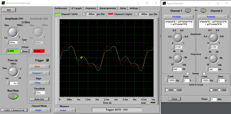
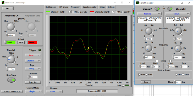
Not very different, just seems that the OD-3 distorts more the signal. It is very clear in the X/Y graphs, obtained in this case for a 250mV signal. The reference signal is of 160mV to keep the signal at similar levels, the difference only affects the angle of the shape. This graph represents the output signal (Y) as a function of the input signal (X), for the whole cycle, that’s why it gives different values for each X. The Y value is the value for that X at a certain instant, and X can have several times the same value in the complete cycle.

In summary, with no distortion at all you obtain a diagonal line, with two sine waves out of phase you get an ellipse and with a distorted signal you get a beautiful shape that can remind you of a signature, a baby, a seahorse… The more distorted the signal, the less similar to a diagonal line it is.

od-3_highsignal_xy
OD-3 XY
tp_highsignal_xy
Tim Pierce XY

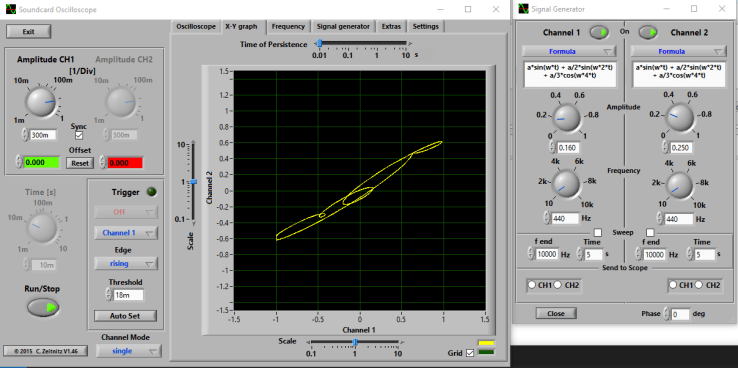
The shape is almost the same for smaller signals at 440Hz and for other frequencies. Tim Pierce Overdrive signal seems to be less distorted, more close to a diagonal line.

Frequency domain

Let’s see now the frequency response, for each one of them and for the stacked set. It has been measured with a soundcard and REW software, with this parameters:

Stepped sine measurement at -20,0 dBFS
1/3 octave, 2 averages, FFT length 65536
0 ms silence
31 measurement points.

Please click on it to zoom:

fr

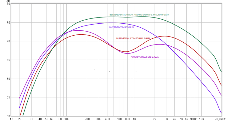
Yellow graph represents BOSS OD-3 response. A more flat response curve (from 100Hz up to 10KHz) compared to the blue line, which represents the Tim Pierce response, more focused on mid range frequencies. The yellow OD-3 line reminds me of the typical Kilimanjaro shape of many amplifiers, with two bumps in low (200Hz) and high frequencies (1KHz), and a slight scoop in between. The high frequencies bump varies a lot when rotating the tone control.

Tim Pierce response is the typical Tubescreamer shape, with a maximum around 500Hz. When stacked (green line), the result is an even more mid rangey tone, with a slight bump at 300Hz.

Summary

After this brief study, I have no idea why I like these two overdrives. Even more, BOSS OD-3 seems more “transparent” or natural to my ear than Tim Pierce Overdrive, but OD-3 is distorting more the signal. I suppose it has to do with the frequency response of the OD-3 compared to the Tim Pierce, which is more open and roughly similar to the response of the amplifier. Or maybe it has to be with the harmonics they are generating, it can also be measured with REW.

When stacked, you notice that the guitar tone cuts through the mix, and it is confirmed by the combined frequency response. That combination will give you that “more” needed for a solo or a particular riff.

BOSS OS-2 Frequency response in different settings

BOSS OS-2 is a good platform for illustrating the difference in frequency response between overdrive and distortion. I have tested my modified OS-2 (see BOSS OS-2 Overdrive/ Distortion MOD) with REW software and my laptop soundcard. It is very simple, you just have to connect the speakers jack to the pedal input and the mic jack to the output. And power the pedal, of course. To make it a little more complex and accurate, I made an adaptor that connects the left channel directly from speaker jack to mic jack and the right channel passes through the pedal. You can configure the software so that the left channel acts as a reference and discount the effect of the frequency response of the sound card itself. Output level has to be kept below some level, in order not to saturate the BOSS buffer, check it with an amplifier connected to the output of the pedal or with an oscilloscope or software tool (more on this in a future post).

REW stands for Room EQ Wizard, and is intended to measure the acoustics of a room and help in equalizing the sound in it. But one of its features is generating a sweep of sine signals and measure the frequency response of a system in front of those signals. While measuring you can see the harmonics, the average 2nd and 3rd harmonic level, and at the end you see the average frequency response for the whole sweep. The software is “donationware” and works in Windows, Linux and MacOS.

Below you can see the different settings I put under measurement:

os-2_blue
Overdrive at max gain, blue

os-2_purple
Distortion at max gain, purple

os-2_green
Distortion at medium gain, red

os-2_red
Blended overdrive and distortion, medium gain, green

And the frequency response of each of the settings:

allfr

As can be seen, distortion settings have a very characteristic “scoop” at middle frequencies (800Hz) that make them more flat sounding. A peak around 100Hz can be seen (and heard as I mentioned in a previous post).

In overdrive settings, on the opposite side, a prevalence of middle frequencies around 500Hz can be seen, what makes it more pleasant and cutting through the mix, as they say.

Combining both (green curve), you have less scoop and the prevalent frequency can be higher, giving more presence to the tone.


BOSS OS-2 Overdrive/ Distortion MOD

I have been playing for two weeks with a BOSS OS-2 overdrive/distortion pedal I found in ebay for repair. Repairing was easy, just needed some pots cleaning.

OS-2 with modified knobs and circuit

The concept is nice: there are two blended circuits:

  • Overdrive, by asymmetrical soft clipping in the feedback loop of an operational amplifier, like most overdrives out there.
  • Distortion by symmetrical hard clipping in the output of the other operational amplifier of the same chip.

You can blend the two by rotating a “color” control, from overdrive on the left to distortion on the right. After the blend section, there is a tone one. The “Drive” pot is a dual 270k potentiometer, each unit connected to the feedback loop of each of the amplifier units.

Out of the brown box (it didn’t come with the original BOSS box) I found some things I didn’t like:

  • Little bass response in the overdrive mode, too much treble for my liking. Usable for me, but could be improved (from my point of view, for my own needs).
  • I usually don’t like pure distortions and hard clipping, so I didn’t expect to like this side too much. I found it too flat and hissing, with little mids, but having a nice boost in the 100Hz (aprox) freq.
boss_os-2_orig
BOSS OS-2 Original circuit


I think there are almost no “bad designs” or “bad pedals” out there, it is just a matter of taste. Many like pedals that I hate (don’t want to give names). Maybe the best overdrive or distortion pedal is no pedal at all, but for people like me that usually don’t play on stadiums, distortion pedals are a good tool to get close to the tone of your favorite player.

Moreover, when you modify a pedal, you are not improving the design, but improving your particular unit for your particular taste. Most components vary a lot in value from unit to unit, and manufacturers have to take many constraints into consideration in their designs. Therefore I think we have to be humble when “improving” a device.

That said, in this case, I considered these objectives:

  • Distortion side:
    • Raising mids and cutting that hiss
    • Trying asymmetrical clipping in this kind of circuits, just for fun
  • Overdrive:
    • Raising mids too, and add some more bass response
    • Trying leds clipping for a supposedly more natural overdrive, and also for fun

After some tweaking and some regrets, I performed to the following changes:

component old value new value why
U2 (opamp) JCR1458D JCR4558D JCR4558D has better characteristics:
1458D
Input Resistance = 1M
Slew Rate = 0,5V/uS4558:
Input Resistance = 5M
Slew Rate = 1V/uSSlew rate affects the circuit bandwidth higher limit, in this case from 8KHZ to 16KHz. Maybe it is overkill, but I think this gives more freedom at adjusting the frequency response of the circuit.
C6 1nF 2n2F Initially, I removed it but after Charles Willis suggestion, I replaced it for a 2.2nF capacitor. It should give more bass in the output of the tone stack.
C27 47nF 220nF Lowers freq. in high pass filter at the input of the overdrive section -> more bass
R39 100 150 Lowers gain in overdrive. See C23
C23 4.7uF 2.2uF In combination with R39, it forms a high pass filter, attenuating frequencies below the cut-off frequency. The modification changes the pass freq from 338Hz to 482Hz. In combination with the C27 change, it results in more mids
D7,D8,D9 Junction diodes D7,D8=Red LED – D9=BAT46 (Schottky) It changes the form of the clipped signal. Red LEDs have Vf=1.8V (instead of 0,7) and different I/V curve. I put a schottky just to experiment, another kind of diode can be used, or just a cable for symmetrical clipping. Another LED would be too much Vf and can result in no clipping
R2 20K 68K This resistor is part of the circuit that balances overdrive and distortion. Since LEDs are used for clipping, the output voltage of the operational is too much when compared to distortion output. Raising the value of this resistor lowers the output of the overdrive section. R13 at the end of the distortion circuit can be lowered too, but that raises the cut-off frequency of the low pass filter formed by R13 and C8, not contributing to eliminate the hiss
C16 18nF 22nF Lowers the cut-off frequency of the high pass filter after the hard clipping section, raising mids in the overall circuit
D3,D4 Junction diodes D3=1N4148 – D4=BAT85 (Schottky) + 10 Ohms resistor It changes the hard clipping section from symmetrical to asymmetrical. The schottky + resistor gives a smoother I/V curve than the diode alone. Just an experiment (successful for my ears), as in the soft clipping section
C8 820pF 4.7nF Lowers the cut-off frequency of the high pass filter after the hard clipping circuit. This is key to cut the hiss
boss_os-2_mod
BOSS OS-2 Modified circuit


Lessons learned

At first I tried LEDs also in the hard clipping section, getting a not so nice result. Probing the circuit with the oscilloscope, I discovered that it was not clipping at all, you could remove the diodes and get the same output. Forward voltage is so high, even for red LEDs (different color LEDs have different Vf), that it didn’t clip at all. The distortion came from the saturated transistor and was not very pleasant.

Then I tried different combinations of Schottky and junction diodes (I like Schottky diodes lately…) until I got to the above blend.

I tried green and blue LEDs and combined LEDs with junction and Schottky in the soft clipping section, but I didn’t like the results. If you have read my other post about SD-1, green and schottky was my final combination in the BOSS SD-1, but it does not seem to work in the OS-2. The final combination was the nicer for my ears, just that.

I put a trimpot instead of R13, in order to adjust the output of the distortion circuit, but the result was catastrophic: more hiss and even oscillation when the trimpot got near zero ohms. So I changed R2, getting much better results.

As you can imagine, the values of the capacitors and resistance are not casual, I have tried many combinations and calculated some filter frequencies to get to those values. Some starting points came from forum posts and some other pages, and I changed some components and at the end returned to the original values (C26 for instance) . The lesson here is: calculate values for the filters involved and act with a purpose. I took some ideas from this post: https://www.roboticbeast.com/modification-de-la-boss-os-2/ but some didn’t wotk for me or with my unit. Another lesson (I already knew, of course) is that every modification affects the whole circuit in some measure, so you shouldn’t change a single component and see if you like it.

Also found a very useful tools for analyzing frequency responses by generating signals and capturing the output of the pedal with a computer and its sound card, more on this in some future post.

PD: if you make this mod, please comment below, I would like to keep track of people enjoying (or not) my mods.

Asymmetrical Octaver Effect

In a previous post, I told how I made an EQD Tentacle Clon in a 1590 Enclosure. I took the layout from http://tagboardeffects.blogspot.com.es/2016/11/earthquaker-devices-tentacle.html and made some minor changes:

  • I used NPN transistors with a high beta (>400), I think they will give higher input gain and more output gain in the final stage.
  • I had a very anoying noise in this circuit from a cheap power supply. Added a 56 Ohms resistor between supply 9V and circuit and the noise disappeared completely. It seems that the 100uF capacitor was not enough and needed a little resistor to absorb the noise.
  • Ommited the two bottom rows with no function.

Yesterday a made a new, more drastical change: I swapped one of the two rectifier diodes (1N4148, Vf = 0.7V) with a BAT46 Schottky diode, with Vf = 0.3V, just to experiment with this component.

The electrical result is an asymmetrical rectification of the input signal, as can be seen in the oscilloscope:

IMG_20181004_134811
input signal below, output signal above

The audible result is a more natural sounding octave effect. Usually octavers have to be combined with overdrives or fuzzes in order to be bearable. Otherwise they sound too robotic and are unusable, at least for me. With this change, even if visually does not seem to be very different from its symmetrical counterpart, at least for my ears it sounds like a very dynamic distortion, and of course gets improved with some kind of light distortion after it.