Not long ago I acquired a TC Electronic Mojomojo on ebay in perfect conditions. I love the brand and wanted to try their analog overdrive pedal. I liked it and kept it, some people complain it is bland, or dark, or anything, but I think in the right ecosystem it can perform very well. I have to confess that it has only be used a few times, just because lately I am using my modified DS-1, BOSS OD-3 or Tim Pierce Overdrive. Maybe I have too many overdrives?
Yesterday I put it on my home pedalboard for some recording, and it sounded really really bad, with very low volume and an unbearable noise. Ok, let’s fix it. Oh, well, it is SMD! Do you know what SMD is? Those pretty boards with tiny little minuscule components. They are not easy to troubleshoot or fix, components are too close together and are not mounted through holes but soldered right on the surface (hence the name: Surface Mounted Devices).
This was not the first time I fix a SMD circuit, I have replaced some USB connectors, and not long ago I fixed a black MXR 6 band equalizer bought broken on ebay. Not impossible, but as I mentioned, components are very small, the board is usually multilayer, and soldering and desoldering is not easy. To make things a little harder, I couldn’t find Mojomojo schematic. When I bought it, I immediately opened it to see what was inside, and although didn’t have the time to trace the complete circuit, I could see it is based on soft symmetrical clipping with four bipolar diodes, a là Vemuram Jan Ray, Tim Pierce, Blue Note, to mention some.
After tracing the clipping operational surroundings and testing the implied components, could see that one of the diodes was behaving abnormally. The oscilloscope gave different lectures for the connection between diodes of the two clipping sections (positive and negative), and it could be explained by a faulty diode. Some additional tests and the diode was located. I was lucky because if the problem had been on some capacitor or in the tone stack it would have been much harder to fix.
Now the problem was that I didn’t have SMD diodes, I am in quarantine because of coronavirus and wanted to fix it soon. So, why not making a virtue of necessity and try some modification of the pedal?
First I soldered a conventional through hole bipolar diode similar to the faulty one to confirm that it was the only problem around, with success. The pedal was alive again.
Now let’s decide about what to drop instead of the faulty diode. I didn’t want to replace any other components because of the lack of schematic and the intrinsic difficulty of replacing SMD components. Since I have experimented before with symmetrical clipping against asymmetrical clipping, it is not hard to guess that the replacing component had to be a different kind of diode. To make the clipping more open and asymmetrical at the same time, a LED was the perfect option. Common bipolar diodes have Vf = 0.6 V, while red LEDs have Vf = 1.2 V. Vf means forward voltage, that can be simplified as the minimum voltage that needs the diode to conduct a significant amount of current. That current is what makes clipping possible because the moment the audio signal reaches Vf, signal voltage starts to be limited. The higher the Vf for the clipping, the higher the signal can get before being clipped. In fact the clipping is not a all or nothing thing, but responds to a curve that is characteristic of each kind of diode.
In our original Mojomojo circuit, we had two diodes for the positive part of the signal and two diodes for the negative part. Total Voltage for clipping was 0.6 + 0.6 = 1.2 V. With a red LED replacing one of the four diodes, we will have 1.2 V in one direction and 0.6 + 1.2 = 1.8 V in the other. Why a red LED and not green, blue or yellow? Red ones have the lower Vf of all visible colors.
Red is a good choice for making it assymetrical and more open, but not too much. Sometimes, especially for mild overdrives, the total Vf is so high that you have no clipping at all. I think 1.2 V versus 1.8 V is a good balance.
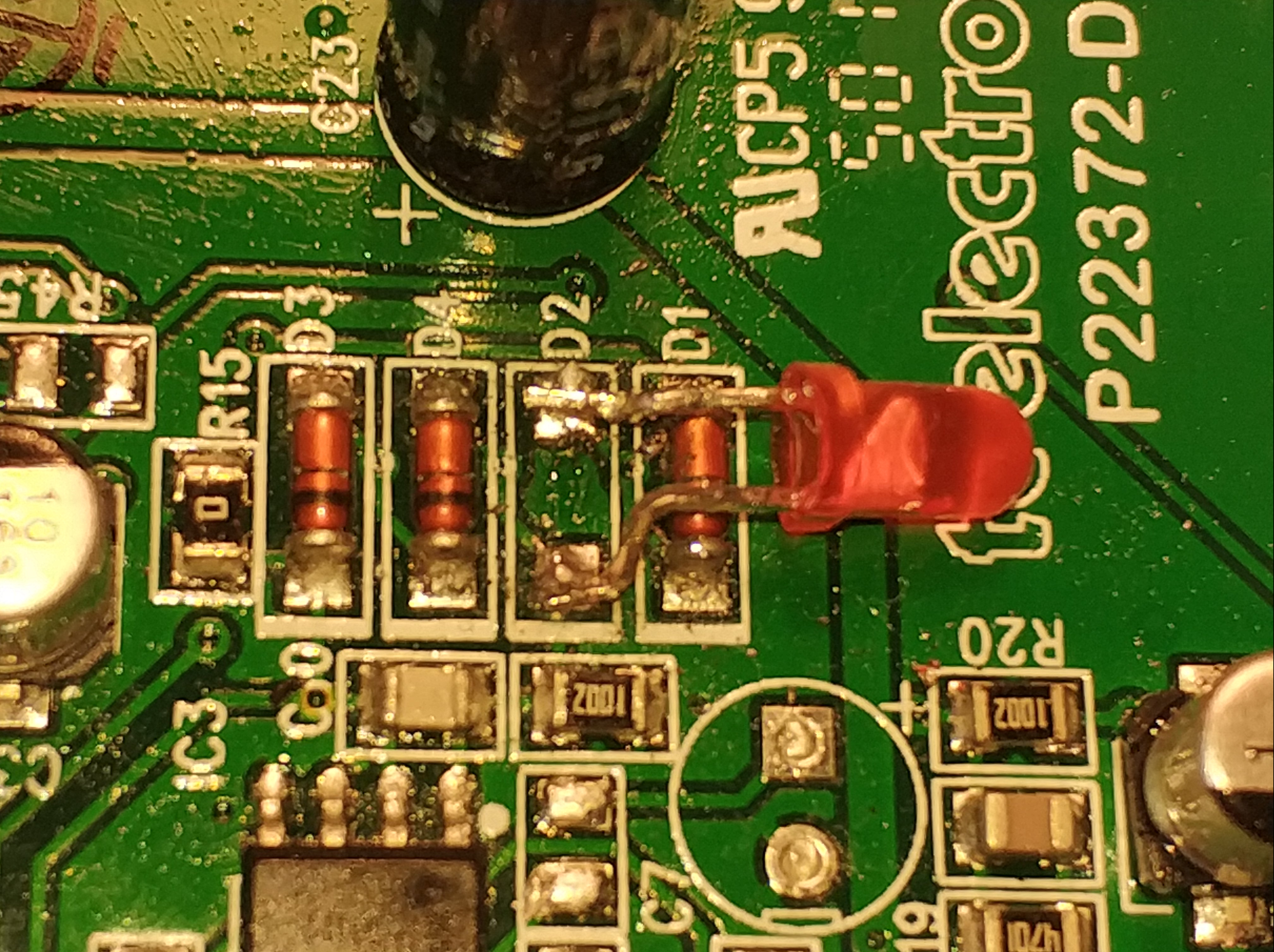
The LED needs some shaping in order to be soldered on the surface of the board.
Shaping the mini LED for SMD soldering
Red LED replacing an SMD diode
We have to be very careful and not let it contact any other component. As usual, but a little harder. Finally some hot glue to make it more resistant mecanically:
How does it sound? I didn’t have a recording of the original sound of my particular Mojomojo, and I think it is not very useful to upload a demo because the difference is subtle, to my ears it gives a little more mojo to the Mojomojo, or at least a different mojo. Some more high end and dynamics and less compression, given the higher Vf. Another LED colors can be tried, of course. Maybe I upload several demos of this and other mods in another post. But I don’t believe very much in online demos, they depend too much on the rest of the gear, and the player itself, of course.
In my previous post https://electric-safari.com/2019/03/17/turn-a-boss-ds-1-into-a-nice-overdrive/ I converted the DS-1 distortion pedal into something very close to an overdrive. One of the things I changed was the clipping section; one of the diodes was replaced by a red led. I tried some other combinations, but not very scientifically, honestly. The final one was chosen by ear, and that’s the one I published. But the doubt about some other combinations remained in my head after that.
Recently I got another DS-1 in ebay, and after modifying it (following my own instructions), I decided to give it another twist: let the user decide what diode to use (or no diode at all) for each side of the clipping section. In the next diagram I show how I connected two rotary selectors for choosing the diodes:
The X and Y terminals from the diagram above have to be connected to one of the removed diodes terminals in the PCB (see the white and blue cables):
It is not necessary to connect anything to the other diode because the two diodes are connected cathode to anode and anode to cathode. Don’t connect one of the terminals to ground, as you could do with some other hard clipping designs (ProCo Rat, for instance) because that is not how they are connected in the DS-1.
The result:
The two selectors act (as I have connected them for my own convenience) as two “taps” for the two sides of the signal (positive and negative), as seen from the supply jack side of the pedal. Open the tap and you have a more open (less clipped) signal, close the tap and you have a more clipped signal. The sequence of clipping goes like this:
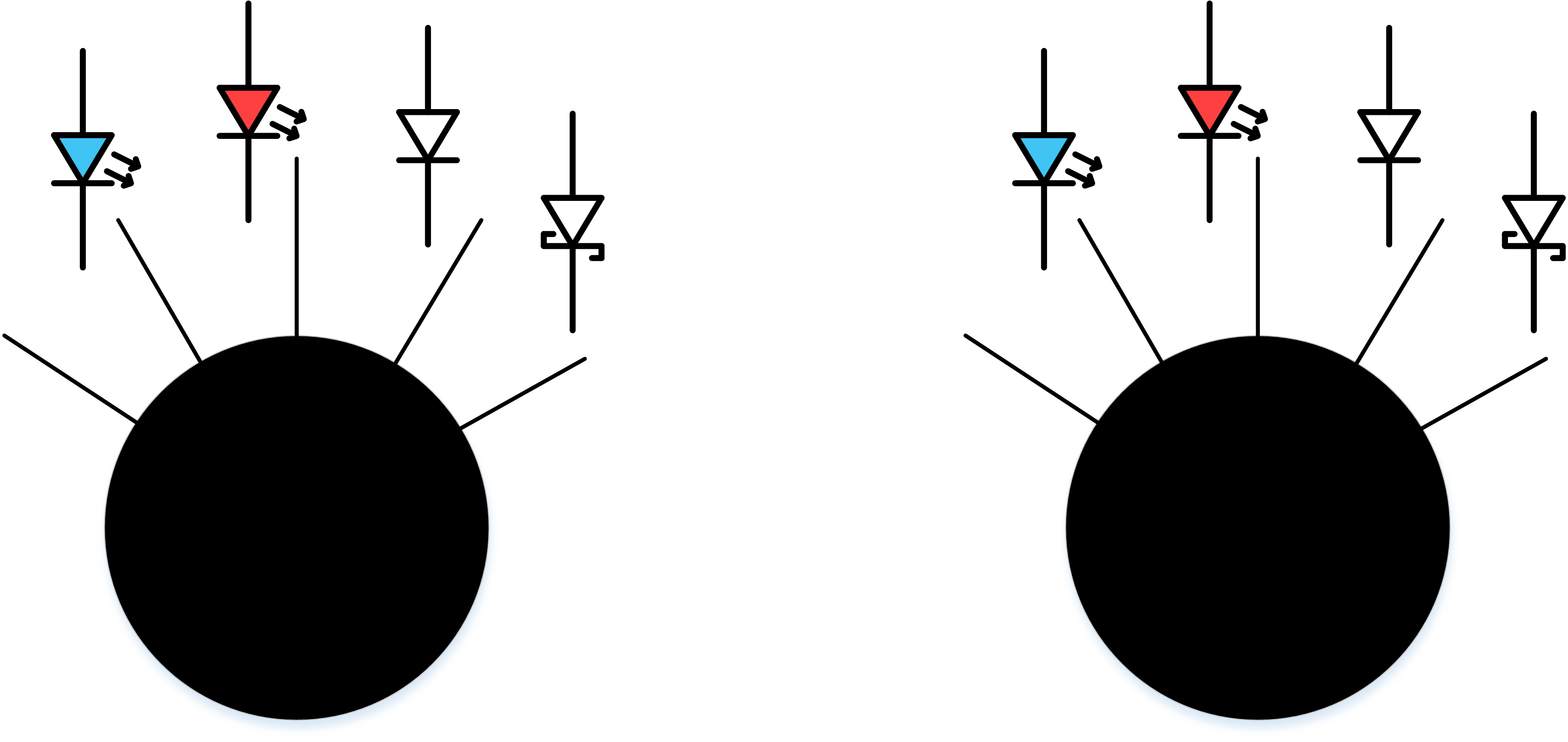
wide open, left position: no diode for clipping. The clipping comes from the transistor section and the operational
second position from the left: blue led, Vf=2V
third position from the left: red led, Vf=1.5V
fourth position from the left: original diode: Vf=0.5V
fifth position from the left: schottky diode: Vf=0.2V
Seen from the front, as you play, you can think about left=less volts / right=more volts.
You could say: there are repeated combinations, because for instance “red led + schottky = schottky + red led”, so I could have chosen a 15 positions (I think) rotary switch for all the valid combinations. Apart from the fact that a 15 positions switch is hard to find and it would have complicated the cabling, that hypothesis (“red led + schottky = schottky + red led”) is not completely true in the real world, because of two reasons:
Let’s face the truth: two different diodes with the same name do not have exactly the same Vf, not to mention the rest of the specs.
Clipping the positive part of the signal is not the same as clipping the negative part of the signal, because of the non linearities of the circuit design and components.
I think that setting two selectors is (as least for me) more intuitive. This is mostly an experiment that can be used also for gigging.
How does it sound
Yes, an experiment, but also a gigging pedal I am planning to use. In spite of the flexibility given by the two selectors, it doesn’t lose its original character. Selecting the combination: position 2 + position 3 (original diode + red led) it sound almost like the other DS-1 I modified, as expected, given the intrinsic differences of every unit components.
Selecting different positions for each selector, especially if they are very extreme, accentuates the asymmetrical character of the distortion (even harmonics, more on that here: https://blackstoneappliances.com/dist101.html)
The blue led combined with any other diode gives a very mid rangy character for my ear.
As you “open” the “tap”, the signal is louder. Selecting the open – open combination creates, as expected, a very loud but distorted signal, not bad given the fact that it is created by the transistor and the operational. Cannot be used as a clean boost pedal, but can crank a tube amp.
At the other extreme, selecting the two schottky diodes and maxing the distortion control creates an almost fuzzy distortion. If you max the three pedal controls, select a neck humbucker pickup and lower the guitar tone control, the fuzz is there for you to enjoy. That way all the treble harmonics that you hear come from the pedal itself, not from the pickup.
Please let any thoughts in the comments section, and if you try this mod please let me know.
The DS-1 mod I mention above (Turn a BOSS DS-1 into a nice overdrive) has been implemented at least by two friends of mine (thanks Pepe and Juanjo for trying it out), and they are very happy users of it, I think they are even gigging with it. They call it “warrior mod” because of my last name in spanish.
I have tested them using a Linux computer, its sound card and qloud software. I know the measurement is not very precise, but the real thing is not going to vary very much, I think. All controls were at noon during the measurement.
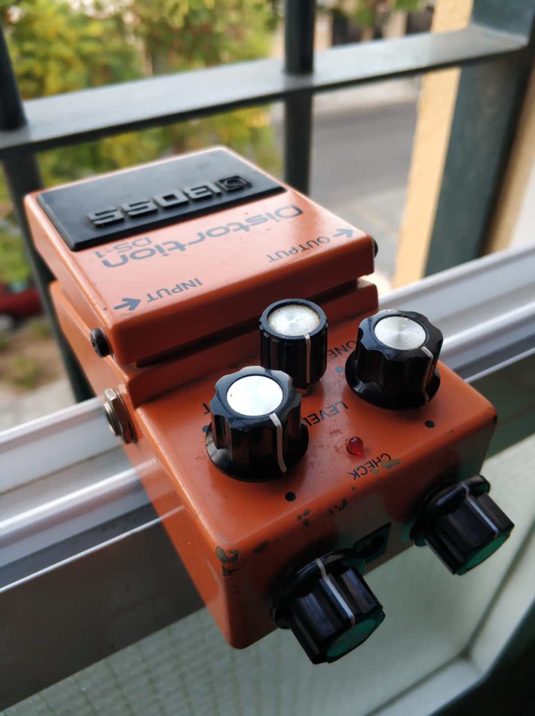
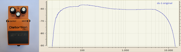
Original BOSS DS-1
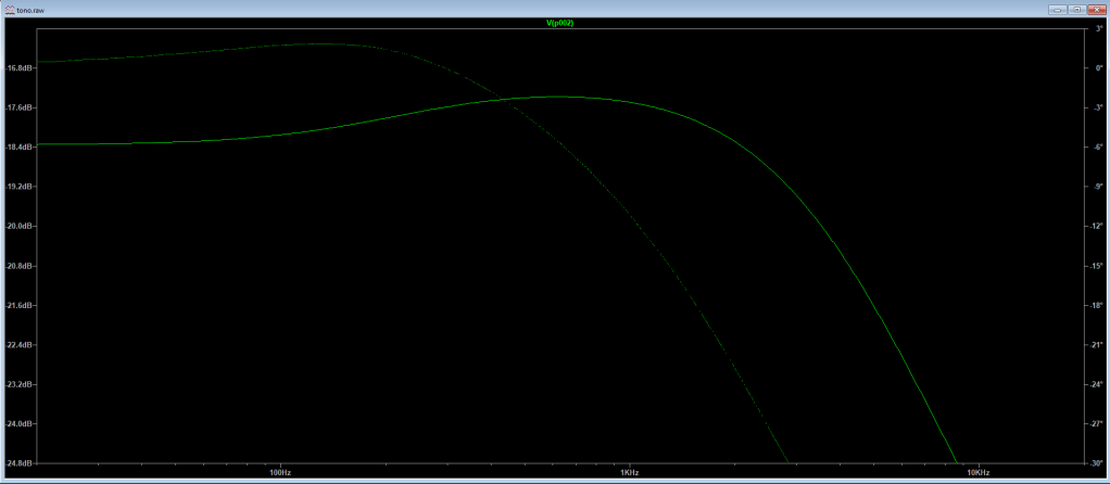
Original DS-1 frequency response
As expected from a pure distortion effect pedal, frequency response is mid scooped, with a bump at 100Hz.
Modified BOSS DS-1
Modified DS-1 frequency response
As I expected after the modifications in the tone stack, frequency response has much more mids. The maximum is not at 800Hz, just because the circuit is not only the tone stack. By touching the tone control, the curve can be modified (I leave it for a next article).
As you can see also, at aproximately the same “level” value, the overall volume is higher (over -60dB for a wider range in the test), without changing any measurement parameter, even if the perceived distortion is higher in the original unit. The reason, I guess, is the red led in the clipping section instead of a common diode, see the article https://electric-safari.com/2019/03/17/turn-a-boss-ds-1-into-a-nice-overdrive/. Since the Vf of the led is higher than that of the diode, it clips at a higher voltage, giving the circuit more headroom. This is very common when doing this kind of modifications. I think the tone stack change alone does not explain that higher volume.
The fence that separates distortion and overdrive pedals is very thin. Usually pedals based on hard clipping, high amount of distortion and mid scooped response curve are called distortion and those ones based on soft clipping and mid boosted are called overdrive. But some of the more famous overdrive pedals, known for being “transparent”, “clean” or “dynamic” are based on hard clipping (clipping diodes at the output of an operational amplifier or transistor). Think of Klon Centaur, for example (mid boosted, by the way).
Hard clipping seems to have usually a more dynamic overall response to the guitar touch than soft clipping, although it depends on the circuit design. Some soft clipping pedals are very dynamic while others are too compressed, but most of them seem to be compressing and distorting all the time.
Hard clipping, theoretically limits drastically the signal when it reaches a certain level, so it creates those high harmonics that give it its character. Soft clipping limits the signal more gradually, giving that “soft”, characteristic valve-like distortion sound.
Having taken all these considerations into account, let’s review my last pedal modification. I wanted to experiment those concepts with a BOSS DS-1 pedal I purchased broken and then fixed. I liked as it was, but that kind of distortion is not for me, frankly.
BOSS DS-1 is based on classical symmetrical hard clipping, two diodes at the output of an operational, and the tone stack tends to mid scoop the response curve, so it should be considered a distortion pedal. It is orange and is called “Distortion”, so in this case it was easy.
My experiment had these objectives:
Reducing distortion (amount of clipping)
Give it an asymmetrical clipping character, more pleasant to my ears and more valve-like distortion
Mid boost the response curve
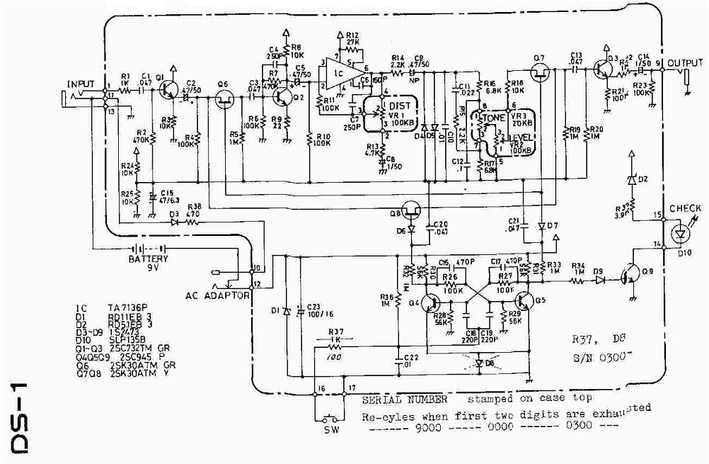
DS-1 original schematic
For reducing distortion, I have made these two changes:
R9 at the emmiter of Q2 controls the gain of the first stage, previous to the opamp stage. With a value of 22 Ohms, the output is so high that the signal at the output of the operational is almost always clipped. I tried with different values and for me 100 Ohms gave the sweet spot for having the right amount of distortion with the gain control at 12 o’clock, for both single coil and humbucker pickups.
LED diodes have a Vf higher than common bipolar diodes. Bipolar diodes have Vf=0.7V and LED have Vf > 1.5V, depending on the color. Vf is what causes the clipping, and the higher Vf is, the higher the signal can be before it starts to clip. Replacing only one of the clipping diodes (D5 for instance) by a red LED yields more headroom and at the same time serves my second purpose of having asymmetrical clipping. By the way, this is one of the changes that the famous Keeley Ultra Mod makes to the DS-1.
For the mid boost thing, I changed several components of the tone stack. DS-1 tone stack is based on the Big Muff tone stack. It is passive and tends to mid scoop the tone. By simulating the circuit with LTSpice, I found the spot where the signal is mid boosted without loosing the ability to control the tone (although it is somewhat reduced compared to the original DS-1 design).
Modified DS-1 tone stack
The bump happens at 800Hz, which for me is the best point to get a nice tone that is capable of cutting through the mix in a band context. It is a simplification because the response curve of the pedal depends on the rest of the circuit as well, but I can tell you that the result is quite acceptable.
The components replaced in the tone stack are C11, C12, R15 and R16. As you can se, only six components have been replaced. I have prefered to keep it as simple as posible, but the change in tone and behavior is drastical. Now the pedal is a very dynamic, mid boosted overdrive, with a wide range of distortion. With gain at max level, it reveals it true distortion spirit. Put a compressor before and an equalizer that boosts the 100Hz frequency after it, and you’ll get the real sound of rock and roll.
As a summary, these are the replacements:
component
original
mod
R9
22 Ohms
100 Ohms
D5
1N4148
Red LED
C11
22nF
33nF
C12
100nF
82nF
R15
2.2K
3.3K
R16
6.8K
1K
For C12, 82nF is not a very common value, but you can put 47nF and 33nF in parallel to get 80nF, enough given the usual tolerances of capacitors. Use a capacitor tester if possible to get a close value. The board has plenty of space to put the two capacitors in that position. For C11 and C12, any kind of capacitor will do, but the values are very important (test if possible).
I hope you enjoy this mod, please let me know of any improvements or mistakes you may find. If you are a good guitar player, please record a demo and upload it to youtube. If you are rich, please send me a Klon Centaur to compare with my DS-1 modified pedal.
PD: if you make this mod, please comment below, I would like to keep track of people enjoying (or not) my mods.
PPD: JAVIER from Argentina made some changes to this mod, he used a 47nF for C12 and a 15K for R15, getting very similar results. Simulating his circuit, we get a very similar curve but smoother, less prominent at 800Hz, and also seems to attenuate high frequencies more:
C12 = 47nF R15 = 15K
Try this if you find the mod too nasal sounding or get some hiss through your amp.
Convierte el BOSS DS-1 en un buen overdrive
La frontera entre pedales de overdrive y de distorsión es más bien fina. Normalmente los pedales basados en hard clipping, mucha distorsión y una curva de frecuencias “mid-scooped” (frecuencias medias rebajadas) son denominados “distorsión”, y aquellos basados en soft clipping y con resalte de medios son llamados “overdrive”. Pero algunos de los overdrives más famosos, conocidos por ser “transparentes”, “limpios” o dinámicos” están basados en hard clipping (cortar la señal en los extremos mediante diodos puestos a tierra a la salida de un operacional). Pensad en el Klon Centaur, por ejemplo (con los medios resaltados, por cierto).
El hard clipping parece tener una respuesta general más dinámica al toque de la guitarra que el soft clipping, aunque depende mucho del diseño del circuito. Algunos pedales con soft clipping son muy dinámicos mientras que otros comprimen demasiado, y la mayoría parecen comprimir a la vez que distorsionan.
El hard clipping, teóricamente limita la señal cuando alcanza cierto nivel, de manera que crea los armónicos en altas frecuencias que le dan ese carácter. El soft clipping limita la señal más gradualmente aportando ese sonido más suave que generalmente asociamos con la distorsión de válvulas.
Teniendo en cuenta todas estas consideraciones, veamos mi última modificación de pedal. Quería experimentar estos conceptos con un BOSS DS-1 que compré averiado y que arreglé. No me disgustaba tal cual, pero ese tipo de distorsión no es para mí, francamente.El BOSS DS-1 está basado en el clásico hard clipping simétrico, dos diodos a la salida de un operacional, y la sección de tono tiende a dar una respuesta “mid scooped”, así que debe ser considerado como un pedal de distorsión. Es naranja y se llama “distortion”, así que en este caso es fácil de clasificar.
Mi experimento tenía estos objetivos:
Reducir la distorsión (cantidad de “clipping”)
Darle un carácter asimétrico, más agradable a mis oídos y más parecido a la distorsión de válvulas
Resaltar los medios en la curva de respuesta de frecuencias
DS-1 original schematic
Para reducir la distorsión, he hecho estos cambios:
R9 en el emisor de Q2 controla la ganancia de la primera etapa, previa al operacional. Con un valor de 22 Ohms, la salida es tan alta que la señal a la salida del operacional es limitada por los diodos prácticamente siempre. Probé con diferentes valores y el de 100 Ohms parecía ser el punto justo para tener la cantidad de distorsión requerida con el control de ganancia a las 12 en punto, tanto para single coils como para humbuckers.
Los diodos LED tienen una Vf (corriente directa) más alta que los diodos bipolares comunes. Los diodos bipolares tienen Vf=0.7V y los LED tienen Vf > 1.5V, dependiendo del color. Vf es lo que provoca el clipping, y cuanto más alto es Vf, más alta puede ser la señal antes de que empiece a limitar. Reemplazar solo uno de los diodos (D5 por ejemplo) por un LED rojo deja más espacio para la señal, y al mismo tiempo cumple con el otro propósito de tener clipping asimétrico. Éste es, por cierto, uno de los cambios del famoso Keeley Ultra Mod.
Para el resalte de medios, cambié varios componentes de la sección de tono. La sección de tono está basada en el control de tono del Big Muff. Es pasiva, y tiende a atenuar los medios. Simulando el circuito en LTSpice, encontré el punto en el que se resaltan los medios de la señal sin perder la capacidad de controlar el tono (aunque esta capacidad se ve algo reducida respecto al DS-1 original).
Modified DS-1 tone stack
El resalte se produce a los 800Hz, que para mí es el mejor punto para conseguir un tono agradable y capaz de ser oído en una mezcla en el contexto de una banda. Es una simplificación, ya que la curva de respuesta del pedal depende del conjunto del circuito, pero os aseguro que el resultado es bastante aceptable.
Los componentes reemplazados en la sección de tono son C11, C12, R15 and R16. Como podéis ver, sólo se han reemplazado seis componentes. He preferido mantenerlo lo más simple posible, pero los cambios en el tono y el comportamiento son drásticos. Ahora el pedal es un overdrive dinámico muy rico en medios, con un rango amplio de distorsión. Con la ganancia al máximo, revela su verdadero espíritu de distorsión. Coloca un compresor delante y un ecualizador después que resalte los 100Hz y conseguirás el verdadero sonido del rock and roll.
Como resumen, éstos son los componentes reemplazados:
componentes
original
mod
R9
22 Ohms
100 Ohms
D5
1N4148
Red LED
C11
22nF
33nF
C12
100nF
82nF
R15
2.2K
3.3K
R16
6.8K
1K
Para C12, 82nF no es un valor muy común, pero puedes poner 47nF y 33nF en paralelo para tener 80nF, suficiente dada la tolerances habitual de los condensadores. Usad un medidor de capacidad si es posible para obtener un valor lo más cercano posible. La placa tiene sitio de sobra para poner dos condensadores en esa posición. Para C11 y C12, cualquier tipo vale, pero los valores son muy importantes (comprobadlos si es posible).
Espero que disfrutéis esta modificación, por favor hacedme llegar cualquier mejora o error que podáis encontrar. Si sois buenos guitarristas, grabad una demo y subidla a youtube. Si sois ricos, enviadme un Klon Centaur para compararlo con mi DS-1 modificado.
PD: si hacéis ese mod, ponedlo en los comentarios abajo. Me gustaría saber si la gente disfruta (o no) de mis mods.
PPD: JAVIER desde Argentina hizo el mod con algunos cambios, usó 47nF en C12 y 15K en R15, consiguiendo un resultado parecido. Al simular su circuito conseguimos una curva muy similar pero más suave, menos pronunciada en los 800Hz, y también aparentemente más atenuada en las altas frecuencias:
C12 = 47nF R15 = 15K
Probad esto si la modificación suena muy nasal, o si obtenéis algo de “fritanga” en el amplificador.
Recently I acquired a BOSS OD-3 Overdrive by chance, just because it was being sold by the same vendor than the BOSS OS-2, both to be fixed. Their problem was the same, just the potentiometers needed deep cleaning. I modified the OS-2, but after checking the OD-3 out, I didn’t feel like modifying it. Just started to love it: very natural sounding, following dynamics while playing, the most amp-like overdrive I have had in my hands.
I have played for a while with it and with my other favorite overdrive, the J.Rockett Tim Pierce Overdrive. This is an overdrive based on the typical operational feedback loop soft clipping (like TubeScreamer), very well designed and manufactured, with an additional, very useful and sweet boost. It cleans up very well when playing soft and have the distortion range I need. And because of it I have become a fan of a superguitar player, Tim Pierce.
Both overdrives are amazing, but sound differently, each one is good for each style and situation, and when stacked, you get a very mid rangey, cutting through tone, while not too dirty tone. I feel the OD-3 more dynamic, with more bass response, while the Tim Pierce is more focused on mids and covers a wider distortion range.
The circuits are very different. I don’t have schematics for Tim Pierce, but seems very similar to J. Rockett Animal Overdrive plus the boost circuit they call “Power Amp”, because it is designed to emulate one of Tim Pierce’s favorite amps, the Naylor SD60. Basically it is a Tubescreamer style overdrive with four diodes placed in pairs in the feedback loop of a JRC4558 opamp, and very well chosen values for the different resistors and capacitors to tailor the frequency response. BOSS OD-3, on the other hand, has a very original design I am still trying to understand, based on a two stage diodes clipping with JRC4558 JFET transistors. There is an operational amplifier, used only for tone shaping and signal level raising. You can see below the schematics:
BOSS OD-3
Trying to dig into the differences between the two styles of clipping, I did some measurements with my laptop. First I generated a couple of signals and captured the output with a Oscilloscope software, let’s see the results.
Pedal settings
These are the settings of both pedals for the measurements, they are basically my favorite settings:
BOSS OD-3 and Tim Pierce settings
Time domain
First, let’s see how they react in front of a triangle signal, probably the most simple signal with some harmonics. I have used my soundcard and a great tool called “Soundcard Oscilloscope“. Frequency is 440Hz and level is 100mV, green line is the original signal and red line is the distorted one, for all graphs:
BOSS OD-3 – 440 Hz triangle, 100mV
Tim Pierce – 440 Hz triangle, 100mV
Interestingly, the Tim Pierce seems to almost not distort the signal, while the OD-3 produces a nice gradual clipping of the signal. Working with smaller signals and different frequencies, both seem to be distorting signals as little as 5mV, keeping almost this same shapes. To explain why they seem cleaner to the ear for smaller signals, a more extensive study should be done, with many frequencies and levels and a real or simulated guitar signal.
For this article, I have used a formula that yields a signal with some harmonics, trying to mimic what a guitar output signal could seem like: a*sin(w*t) + a/2sin(w*2*t) + a/3*cos(w*4*t). It is not by any means a guitar signal emulation, just something a little more complex than a triangle-shaped signal.
OD-3 – 440 Hz formula, 100mV
Tim Pierce – 440 Hz formula, 100mV
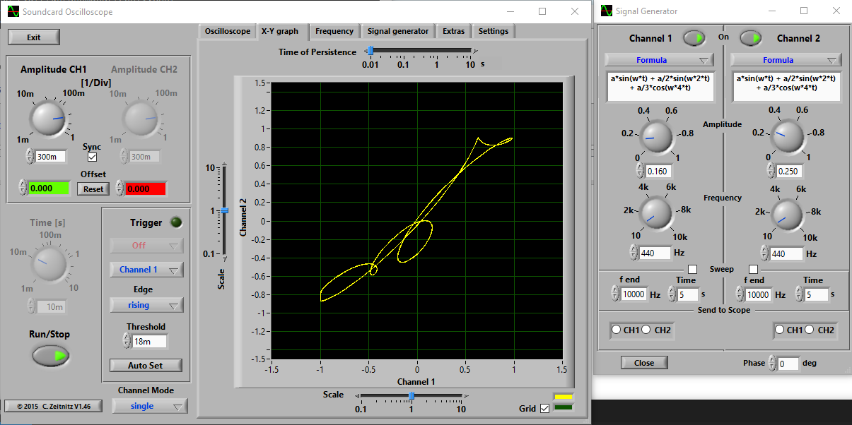
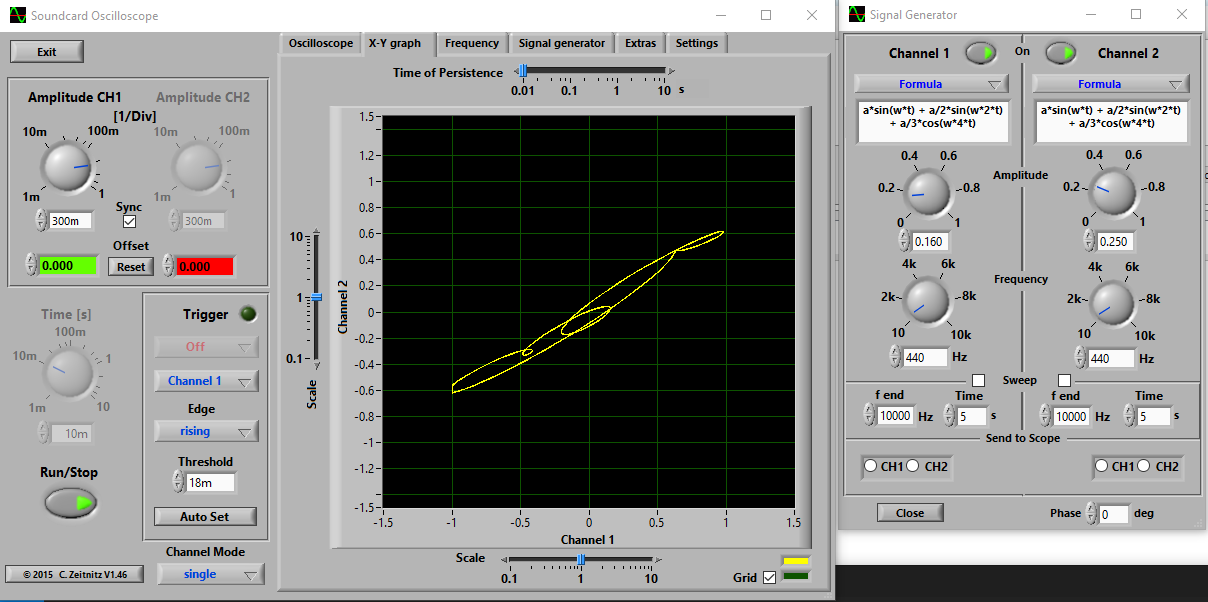
Not very different, just seems that the OD-3 distorts more the signal. It is very clear in the X/Y graphs, obtained in this case for a 250mV signal. The reference signal is of 160mV to keep the signal at similar levels, the difference only affects the angle of the shape. This graph represents the output signal (Y) as a function of the input signal (X), for the whole cycle, that’s why it gives different values for each X. The Y value is the value for that X at a certain instant, and X can have several times the same value in the complete cycle.
In summary, with no distortion at all you obtain a diagonal line, with two sine waves out of phase you get an ellipse and with a distorted signal you get a beautiful shape that can remind you of a signature, a baby, a seahorse… The more distorted the signal, the less similar to a diagonal line it is.
OD-3 XY
Tim Pierce XY
The shape is almost the same for smaller signals at 440Hz and for other frequencies. Tim Pierce Overdrive signal seems to be less distorted, more close to a diagonal line.
Frequency domain
Let’s see now the frequency response, for each one of them and for the stacked set. It has been measured with a soundcard and REW software, with this parameters:
Stepped sine measurement at -20,0 dBFS
1/3 octave, 2 averages, FFT length 65536
0 ms silence
31 measurement points.
Please click on it to zoom:
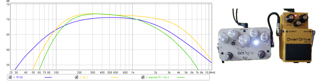
Yellow graph represents BOSS OD-3 response. A more flat response curve (from 100Hz up to 10KHz) compared to the blue line, which represents the Tim Pierce response, more focused on mid range frequencies. The yellow OD-3 line reminds me of the typical Kilimanjaro shape of many amplifiers, with two bumps in low (200Hz) and high frequencies (1KHz), and a slight scoop in between. The high frequencies bump varies a lot when rotating the tone control.
Tim Pierce response is the typical Tubescreamer shape, with a maximum around 500Hz. When stacked (green line), the result is an even more mid rangey tone, with a slight bump at 300Hz.
Summary
After this brief study, I have no idea why I like these two overdrives. Even more, BOSS OD-3 seems more “transparent” or natural to my ear than Tim Pierce Overdrive, but OD-3 is distorting more the signal. I suppose it has to do with the frequency response of the OD-3 compared to the Tim Pierce, which is more open and roughly similar to the response of the amplifier. Or maybe it has to be with the harmonics they are generating, it can also be measured with REW.
When stacked, you notice that the guitar tone cuts through the mix, and it is confirmed by the combined frequency response. That combination will give you that “more” needed for a solo or a particular riff.
BOSS OS-2 is a good platform for illustrating the difference in frequency response between overdrive and distortion. I have tested my modified OS-2 (see BOSS OS-2 Overdrive/ Distortion MOD) with REW software and my laptop soundcard. It is very simple, you just have to connect the speakers jack to the pedal input and the mic jack to the output. And power the pedal, of course. To make it a little more complex and accurate, I made an adaptor that connects the left channel directly from speaker jack to mic jack and the right channel passes through the pedal. You can configure the software so that the left channel acts as a reference and discount the effect of the frequency response of the sound card itself. Output level has to be kept below some level, in order not to saturate the BOSS buffer, check it with an amplifier connected to the output of the pedal or with an oscilloscope or software tool (more on this in a future post).
REW stands for Room EQ Wizard, and is intended to measure the acoustics of a room and help in equalizing the sound in it. But one of its features is generating a sweep of sine signals and measure the frequency response of a system in front of those signals. While measuring you can see the harmonics, the average 2nd and 3rd harmonic level, and at the end you see the average frequency response for the whole sweep. The software is “donationware” and works in Windows, Linux and MacOS.
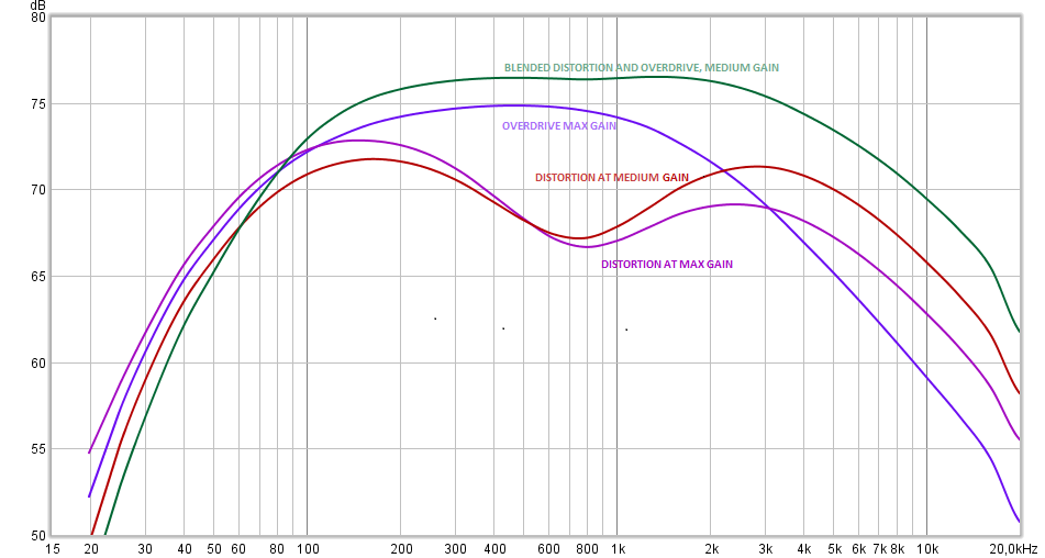
Below you can see the different settings I put under measurement:
Overdrive at max gain, blue
Distortion at max gain, purple
Distortion at medium gain, red
Blended overdrive and distortion, medium gain, green
And the frequency response of each of the settings:
As can be seen, distortion settings have a very characteristic “scoop” at middle frequencies (800Hz) that make them more flat sounding. A peak around 100Hz can be seen (and heard as I mentioned in a previous post).
In overdrive settings, on the opposite side, a prevalence of middle frequencies around 500Hz can be seen, what makes it more pleasant and cutting through the mix, as they say.
Combining both (green curve), you have less scoop and the prevalent frequency can be higher, giving more presence to the tone.
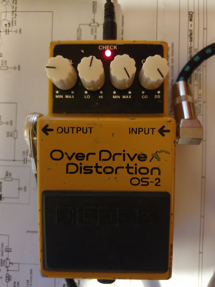
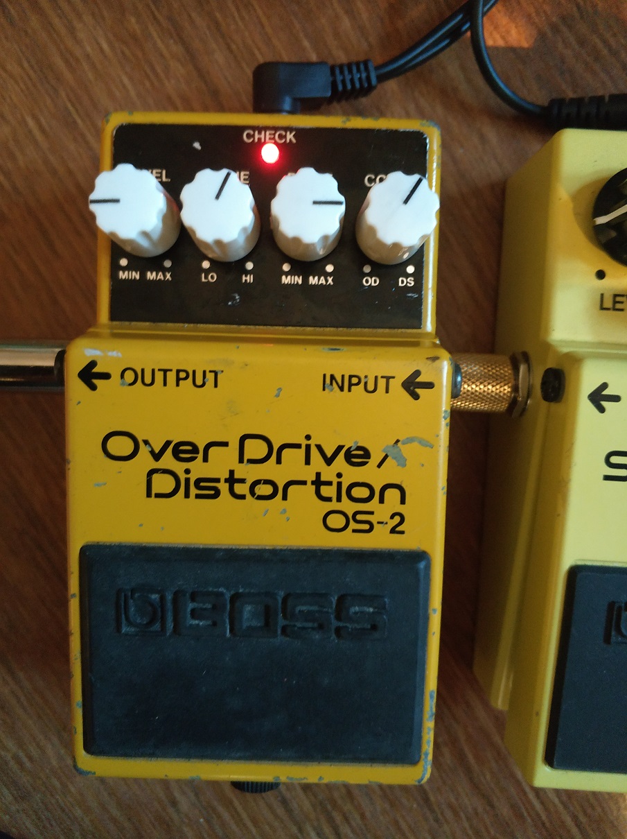
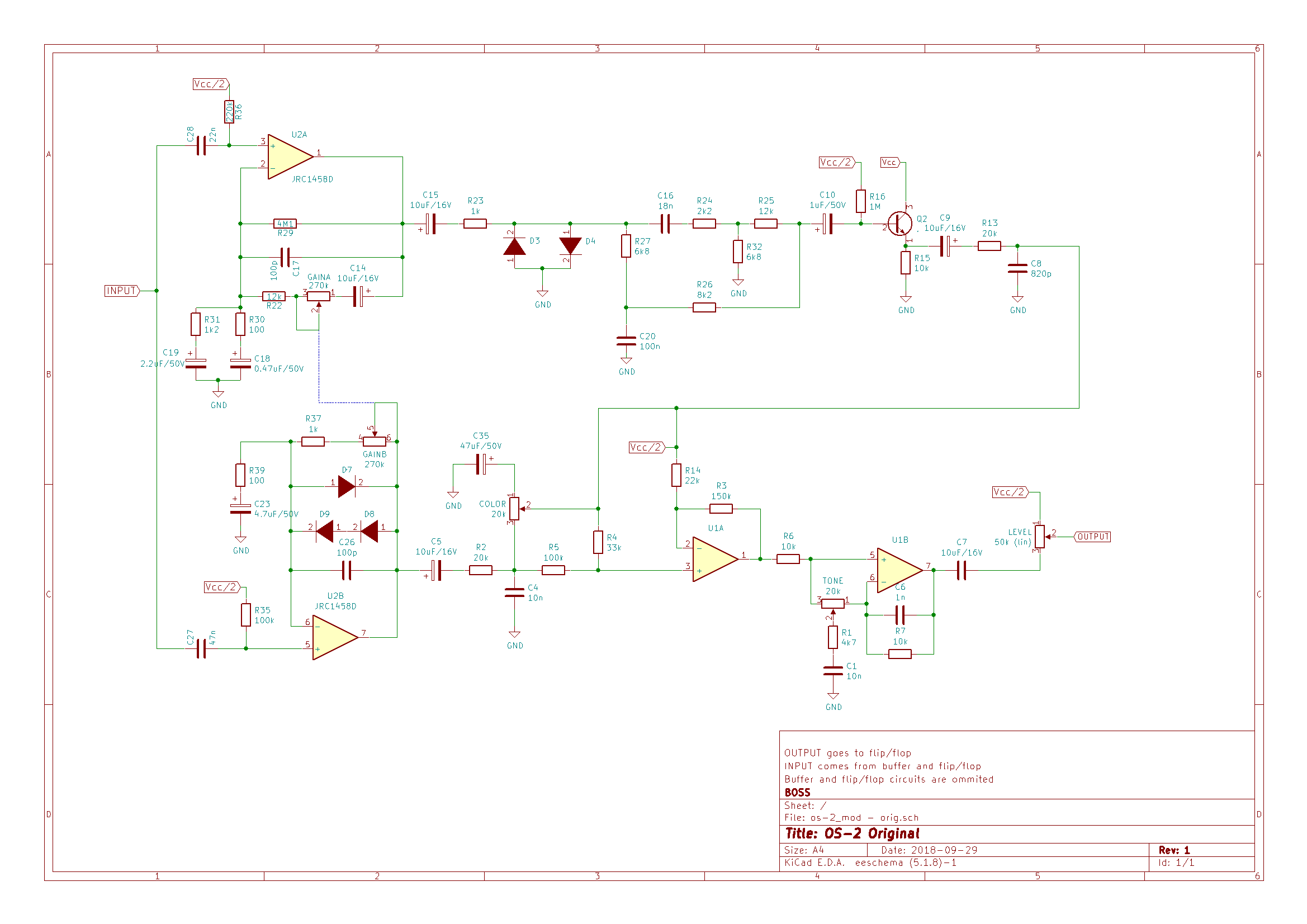
I have been playing for two weeks with a BOSS OS-2 overdrive/distortion pedal I found in ebay for repair. Repairing was easy, just needed some pots cleaning.
OS-2 with modified knobs and circuit
The concept is nice: there are two blended circuits:
Overdrive, by asymmetrical soft clipping in the feedback loop of an operational amplifier, like most overdrives out there.
Distortion by symmetrical hard clipping in the output of the other operational amplifier of the same chip.
You can blend the two by rotating a “color” control, from overdrive on the left to distortion on the right. After the blend section, there is a tone one. The “Drive” pot is a dual 270k potentiometer, each unit connected to the feedback loop of each of the amplifier units.
Out of the brown box (it didn’t come with the original BOSS box) I found some things I didn’t like:
Little bass response in the overdrive mode, too much treble for my liking. Usable for me, but could be improved (from my point of view, for my own needs).
I usually don’t like pure distortions and hard clipping, so I didn’t expect to like this side too much. I found it too flat and hissing, with little mids, but having a nice boost in the 100Hz (aprox) freq.
BOSS OS-2 Original circuit
I think there are almost no “bad designs” or “bad pedals” out there, it is just a matter of taste. Many like pedals that I hate (don’t want to give names). Maybe the best overdrive or distortion pedal is no pedal at all, but for people like me that usually don’t play on stadiums, distortion pedals are a good tool to get close to the tone of your favorite player.
Moreover, when you modify a pedal, you are not improving the design, but improving your particular unit for your particular taste. Most components vary a lot in value from unit to unit, and manufacturers have to take many constraints into consideration in their designs. Therefore I think we have to be humble when “improving” a device.
That said, in this case, I considered these objectives:
Distortion side:
Raising mids and cutting that hiss
Trying asymmetrical clipping in this kind of circuits, just for fun
Overdrive:
Raising mids too, and add some more bass response
Trying leds clipping for a supposedly more natural overdrive, and also for fun
After some tweaking and some regrets, I performed to the following changes:
component
old value
new value
why
U2 (opamp)
JCR1458D
JCR4558D
JCR4558D has better characteristics: 1458D Input Resistance = 1M Slew Rate = 0,5V/uS4558: Input Resistance = 5M Slew Rate = 1V/uSSlew rate affects the circuit bandwidth higher limit, in this case from 8KHZ to 16KHz. Maybe it is overkill, but I think this gives more freedom at adjusting the frequency response of the circuit.
C6
1nF
2n2F
Initially, I removed it but after Charles Willis suggestion, I replaced it for a 2.2nF capacitor. It should give more bass in the output of the tone stack.
C27
47nF
220nF
Lowers freq. in high pass filter at the input of the overdrive section -> more bass
R39
100
150
Lowers gain in overdrive. See C23
C23
4.7uF
2.2uF
In combination with R39, it forms a high pass filter, attenuating frequencies below the cut-off frequency. The modification changes the pass freq from 338Hz to 482Hz. In combination with the C27 change, it results in more mids
D7,D8,D9
Junction diodes
D7,D8=Red LED – D9=BAT46 (Schottky)
It changes the form of the clipped signal. Red LEDs have Vf=1.8V (instead of 0,7) and different I/V curve. I put a schottky just to experiment, another kind of diode can be used, or just a cable for symmetrical clipping. Another LED would be too much Vf and can result in no clipping
R2
20K
68K
This resistor is part of the circuit that balances overdrive and distortion. Since LEDs are used for clipping, the output voltage of the operational is too much when compared to distortion output. Raising the value of this resistor lowers the output of the overdrive section. R13 at the end of the distortion circuit can be lowered too, but that raises the cut-off frequency of the low pass filter formed by R13 and C8, not contributing to eliminate the hiss
C16
18nF
22nF
Lowers the cut-off frequency of the high pass filter after the hard clipping section, raising mids in the overall circuit
It changes the hard clipping section from symmetrical to asymmetrical. The schottky + resistor gives a smoother I/V curve than the diode alone. Just an experiment (successful for my ears), as in the soft clipping section
C8
820pF
4.7nF
Lowers the cut-off frequency of the high pass filter after the hard clipping circuit. This is key to cut the hiss
BOSS OS-2 Modified circuit
Lessons learned
At first I tried LEDs also in the hard clipping section, getting a not so nice result. Probing the circuit with the oscilloscope, I discovered that it was not clipping at all, you could remove the diodes and get the same output. Forward voltage is so high, even for red LEDs (different color LEDs have different Vf), that it didn’t clip at all. The distortion came from the saturated transistor and was not very pleasant.
Then I tried different combinations of Schottky and junction diodes (I like Schottky diodes lately…) until I got to the above blend.
I tried green and blue LEDs and combined LEDs with junction and Schottky in the soft clipping section, but I didn’t like the results. If you have read my other post about SD-1, green and schottky was my final combination in the BOSS SD-1, but it does not seem to work in the OS-2. The final combination was the nicer for my ears, just that.
I put a trimpot instead of R13, in order to adjust the output of the distortion circuit, but the result was catastrophic: more hiss and even oscillation when the trimpot got near zero ohms. So I changed R2, getting much better results.
As you can imagine, the values of the capacitors and resistance are not casual, I have tried many combinations and calculated some filter frequencies to get to those values. Some starting points came from forum posts and some other pages, and I changed some components and at the end returned to the original values (C26 for instance) . The lesson here is: calculate values for the filters involved and act with a purpose. I took some ideas from this post: https://www.roboticbeast.com/modification-de-la-boss-os-2/ but some didn’t wotk for me or with my unit. Another lesson (I already knew, of course) is that every modification affects the whole circuit in some measure, so you shouldn’t change a single component and see if you like it.
Also found a very useful tools for analyzing frequency responses by generating signals and capturing the output of the pedal with a computer and its sound card, more on this in some future post.
PD: if you make this mod, please comment below, I would like to keep track of people enjoying (or not) my mods.
I used NPN transistors with a high beta (>400), I think they will give higher input gain and more output gain in the final stage.
I had a very anoying noise in this circuit from a cheap power supply. Added a 56 Ohms resistor between supply 9V and circuit and the noise disappeared completely. It seems that the 100uF capacitor was not enough and needed a little resistor to absorb the noise.
Ommited the two bottom rows with no function.
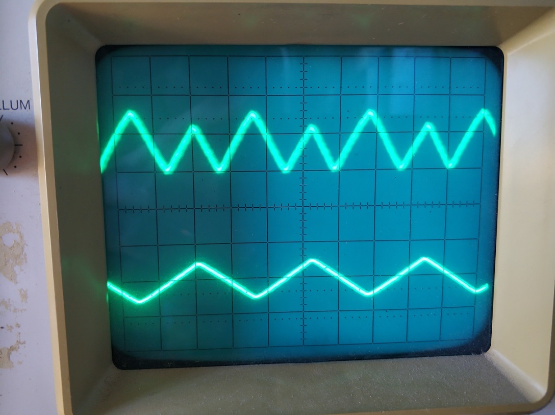
Yesterday a made a new, more drastical change: I swapped one of the two rectifier diodes (1N4148, Vf = 0.7V) with a BAT46 Schottky diode, with Vf = 0.3V, just to experiment with this component.
The electrical result is an asymmetrical rectification of the input signal, as can be seen in the oscilloscope:
input signal below, output signal above
The audible result is a more natural sounding octave effect. Usually octavers have to be combined with overdrives or fuzzes in order to be bearable. Otherwise they sound too robotic and are unusable, at least for me. With this change, even if visually does not seem to be very different from its symmetrical counterpart, at least for my ears it sounds like a very dynamic distortion, and of course gets improved with some kind of light distortion after it.
Out of curiosity, I bought a second hand SD-1, just to try it as is, and try some of the mods people have been doing to this pedal for the last decades. Some mods try to transform it into a TS9 or even a TS808, so you can turn this relatively cheap pedal into a more expensive one. But this box has its own personality, the design is very similar to TS9 but with some remarkable differences:
Clipping is asymmetrical, two diodes forward and one backwards (in the direction of the operational). Asymmetrical clipping sounds different than symmetrical one, some people describe it as harsh or hairy of fuzzy compared to the latter.
There is no capacitor in the feedback loop of the clipping amplifier. This capacitor smooths the clipping a little, giving the TubeScreamer part of its particular tone.
Tone control is very similar but with different component values and with a capacitor (C6) in the feedback loop of the tone control operational amplifier. This capacitor is the first thing I have seen every mod removes because it sucks a significant amount of bass frequencies to the signal.
After trying the pedal for a while, I quickly noticed what most people complain about, this makes the guitar sound thinner. This has not to be bad in every ocasion, especially in live gigs situations where you want to sound in a different spectrum space than the rest of the instruments. But ok, I want more bass too. In this clip I recorded the original sound of the pedal, playing with a RS420 (humbuckers) and a Fender Blues Deluxe amp (please don’t pay attention to the music, just the sound 😉 ):
To correct this defect or feature, there are multiple mods out there, usually people remove capacitor C6 and change values of R6 and C3, which connect the feedback loop and the negative operational input to a voltage divider, in a similar way to he TS9 connects those to ground. lowering R6 and raising C3 values results in more bass response from the clipping circuit. See below the schematic:
BOSS SD1
I chose to make this changes in order to get a nice tone from the pedal:
C6: instead of removing, changed it with a 100pF capacitor from its original value of 10nF.
C3: raised from 47nF to 100nF.
R6: lowered to 3K3
The other section where people make changes is the clipping circuit. Many mods aim in the direction of getting symmetrical clipping, but I didn’t want another TubeScreamer. Instead of that, I wanted to enhance the personality of the effect by exaggerating the asymmetry of the clipping section. Asymmetry comes from using a different quantity of diodes in each direction, or from using diodes with different specifications, especially with different forward voltages (Vf). Vf is different for the following types of diodes:
Ge diodes: low Vf, around 0,3V
Si diodes: usually around 0,6V
LED diodes: depends on the color, 2V for green ones, 1,6 for red ones.
So using a Ge diode in one sense and a LED in the other, we get asymmetrical clipping, right? Right, but Ge diodes are expensive, hard to find and unstable. I read about simulating Ge diodes with schottky diodes in this article:
Ge diodes are used in some mods also because of the smooth I-V curve the exhibit. Schottky diodes have a low Vf too, but the I-V curve is more abrupt than the Ge one. By adding a resistor in series, you can get a similar response, at a lower cost and with more stability.
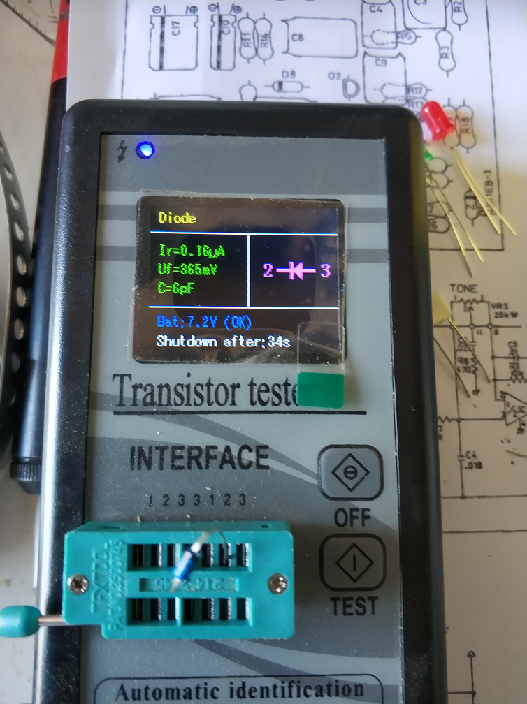
In my mod, I have replaced D5 and D6 (in series in the original circuit) with a resistor (10 Ohms) and a schottky diode (BAT46) with a Vf of 365mV. And D4 has been replaced with a green LED with VF=2V. You can see the measures below:
The components used:
And the changes to make:
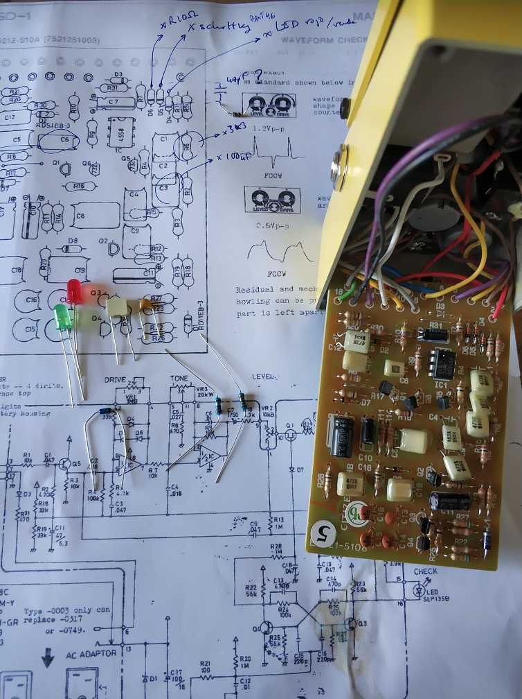
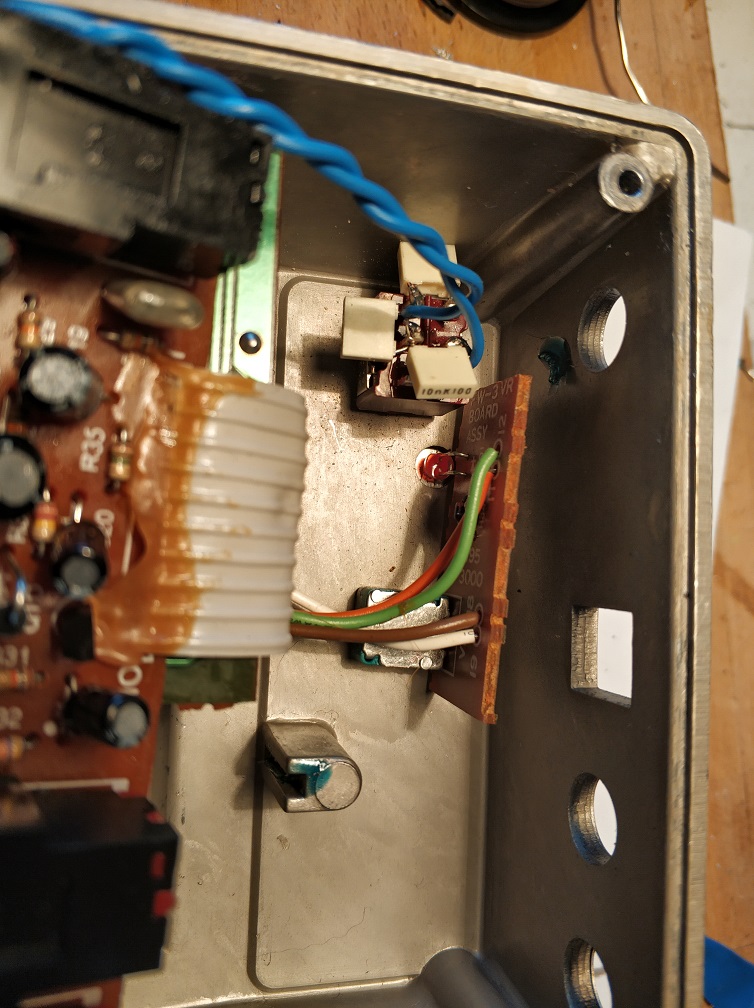
For the clipping section, that I suppose will be subject of further modifications, I have replaced the original components with sockets. In the picture below you can see the other components replaced too:
Here you can see a detail of the changes in the clipping section:
And the result in the following record. I was not trying to play a song, just to get all the possible tones from the pedal. Please forgive me if I get sloppy:
I can perceive these differences after playing for a while:
More volume at the same “level”.
Much more bass frequencies, without being too much for a band situation, I think (has to be tested in a band situation).
More of the asymmetrical character: “harsher” when playing harder, keeping dynamics (I think more than the original, maybe I am somewhat subjective).
I think the sound changes more than the original when moving the drive control: from a smooth, almost TS9-esque overdrive at low gain levels to almost fuzzy and even octave-like at maximum gain.
If you are interested in this mod, please try it, test it and give me your opinion in the comments section. If you improve it, tell me how. If you like it, give me a “like”, and if it’s possible for you, mention my blog to yout friends 🙂 Mods have no copyright, but we like some recognition, don’t we?
Edited on March 16 2019:
Some days ago I put a red led instead of the green one. Now the overdrive is more usable and versatile, although the octave effect is less pronunciated.
PD (May 2 2022):
A more simple modification that makes the pedal even more usable is just changing D4 for a red led and leaving the other diodes as they are. I did this for a friend that wanted a less edgy sound, and the result is better than my original mod.
PD: si hacéis ese mod, ponedlo en los comentarios abajo. Me gustaría saber si la gente disfruta (o no) de mis mods.
In a previous post (BOSS FW-3 Mods) I told how I did some basic mods to a BOSS FW-3 Wah pedal, which is basically a Cry Baby design with a potentiometer for varying the Q.
For the capacitor that controls the sweep range (C12), I chose a value of 0,022uF, to give the effect a very personal lower sweep range. I found it problematic in some situations, because the effectiveness of the variable band pass filter as a musical device is very dependent on the color of the signal that it encounters at its input. For instance, if I am using the brigde pickup in an already bright sounding guitar (tele or strat), playing high pitch notes, a low frequency sweep will let the sound almost without volume at the low end of the range. The same happens in the opposite situation – high sweep range with dark sounding pickups, or lower notes.
So, in order to have an all terrain wah effect, I have put a switch for alternating between three different values:
5nF – higher frequencies sweep range
10nF – the original one
20nF – lower frequencies sweep range
Given the behavior of a DPDT on-on-on switch, you can get those three values and their corresponding sweep range values (see https://www.electrosmash.com/crybaby-gcb-95) using three 10nF capacitors, this way:
Other values can be chosen, of course, to obtain more radical or subtle changes. For instance, with 10nF in the center, 56nF at right and 4.7nF on top you get:
3.2nF – very high range, good for a very bright guitar and higher notes
10nF – original sweep range
66nF – very low sweep, suitable for a bass guitar
The real life device, as built for this project:
As I mentioned in the previous post (BOSS FW-3 Mods), this pedal, apart from being a tank, has space enough inside for storing all the money I have. In this picture you can see how the DPDT switch fits inside the case:
In the main PCB, the cables from the switch are soldered instead of the original capacitor:
And the final result from the outside (the scratches and dents were already there, they are natural relic as this pedal has more than 20 years):
If you have any advice about the execution of the project, or simply have tried it, or in case you had any problem, please let me know in the comments below.
PD: si hacéis ese mod, ponedlo en los comentarios abajo. Me gustaría saber si la gente disfruta (o no) de mis mods.


 he design is very similar to TS9 but with some remarkable differences: