I have tested them using a Linux computer, its sound card and qloud software. I know the measurement is not very precise, but the real thing is not going to vary very much, I think. All controls were at noon during the measurement.
Original BOSS DS-1
Original DS-1 frequency response
As expected from a pure distortion effect pedal, frequency response is mid scooped, with a bump at 100Hz.
Modified BOSS DS-1
Modified DS-1 frequency response
As I expected after the modifications in the tone stack, frequency response has much more mids. The maximum is not at 800Hz, just because the circuit is not only the tone stack. By touching the tone control, the curve can be modified (I leave it for a next article).
As you can see also, at aproximately the same “level” value, the overall volume is higher (over -60dB for a wider range in the test), without changing any measurement parameter, even if the perceived distortion is higher in the original unit. The reason, I guess, is the red led in the clipping section instead of a common diode, see the article https://electric-safari.com/2019/03/17/turn-a-boss-ds-1-into-a-nice-overdrive/. Since the Vf of the led is higher than that of the diode, it clips at a higher voltage, giving the circuit more headroom. This is very common when doing this kind of modifications. I think the tone stack change alone does not explain that higher volume.
Out of curiosity, I bought a second hand SD-1, just to try it as is, and try some of the mods people have been doing to this pedal for the last decades. Some mods try to transform it into a TS9 or even a TS808, so you can turn this relatively cheap pedal into a more expensive one. But this box has its own personality, the design is very similar to TS9 but with some remarkable differences:
Clipping is asymmetrical, two diodes forward and one backwards (in the direction of the operational). Asymmetrical clipping sounds different than symmetrical one, some people describe it as harsh or hairy of fuzzy compared to the latter.
There is no capacitor in the feedback loop of the clipping amplifier. This capacitor smooths the clipping a little, giving the TubeScreamer part of its particular tone.
Tone control is very similar but with different component values and with a capacitor (C6) in the feedback loop of the tone control operational amplifier. This capacitor is the first thing I have seen every mod removes because it sucks a significant amount of bass frequencies to the signal.
After trying the pedal for a while, I quickly noticed what most people complain about, this makes the guitar sound thinner. This has not to be bad in every ocasion, especially in live gigs situations where you want to sound in a different spectrum space than the rest of the instruments. But ok, I want more bass too. In this clip I recorded the original sound of the pedal, playing with a RS420 (humbuckers) and a Fender Blues Deluxe amp (please don’t pay attention to the music, just the sound 😉 ):
To correct this defect or feature, there are multiple mods out there, usually people remove capacitor C6 and change values of R6 and C3, which connect the feedback loop and the negative operational input to a voltage divider, in a similar way to he TS9 connects those to ground. lowering R6 and raising C3 values results in more bass response from the clipping circuit. See below the schematic:
BOSS SD1
I chose to make this changes in order to get a nice tone from the pedal:
C6: instead of removing, changed it with a 100pF capacitor from its original value of 10nF.
C3: raised from 47nF to 100nF.
R6: lowered to 3K3
The other section where people make changes is the clipping circuit. Many mods aim in the direction of getting symmetrical clipping, but I didn’t want another TubeScreamer. Instead of that, I wanted to enhance the personality of the effect by exaggerating the asymmetry of the clipping section. Asymmetry comes from using a different quantity of diodes in each direction, or from using diodes with different specifications, especially with different forward voltages (Vf). Vf is different for the following types of diodes:
Ge diodes: low Vf, around 0,3V
Si diodes: usually around 0,6V
LED diodes: depends on the color, 2V for green ones, 1,6 for red ones.
So using a Ge diode in one sense and a LED in the other, we get asymmetrical clipping, right? Right, but Ge diodes are expensive, hard to find and unstable. I read about simulating Ge diodes with schottky diodes in this article:
Ge diodes are used in some mods also because of the smooth I-V curve the exhibit. Schottky diodes have a low Vf too, but the I-V curve is more abrupt than the Ge one. By adding a resistor in series, you can get a similar response, at a lower cost and with more stability.
In my mod, I have replaced D5 and D6 (in series in the original circuit) with a resistor (10 Ohms) and a schottky diode (BAT46) with a Vf of 365mV. And D4 has been replaced with a green LED with VF=2V. You can see the measures below:
The components used:
And the changes to make:
For the clipping section, that I suppose will be subject of further modifications, I have replaced the original components with sockets. In the picture below you can see the other components replaced too:
Here you can see a detail of the changes in the clipping section:
And the result in the following record. I was not trying to play a song, just to get all the possible tones from the pedal. Please forgive me if I get sloppy:
I can perceive these differences after playing for a while:
More volume at the same “level”.
Much more bass frequencies, without being too much for a band situation, I think (has to be tested in a band situation).
More of the asymmetrical character: “harsher” when playing harder, keeping dynamics (I think more than the original, maybe I am somewhat subjective).
I think the sound changes more than the original when moving the drive control: from a smooth, almost TS9-esque overdrive at low gain levels to almost fuzzy and even octave-like at maximum gain.
If you are interested in this mod, please try it, test it and give me your opinion in the comments section. If you improve it, tell me how. If you like it, give me a “like”, and if it’s possible for you, mention my blog to yout friends 🙂 Mods have no copyright, but we like some recognition, don’t we?
Edited on March 16 2019:
Some days ago I put a red led instead of the green one. Now the overdrive is more usable and versatile, although the octave effect is less pronunciated.
PD (May 2 2022):
A more simple modification that makes the pedal even more usable is just changing D4 for a red led and leaving the other diodes as they are. I did this for a friend that wanted a less edgy sound, and the result is better than my original mod.
PD: si hacéis ese mod, ponedlo en los comentarios abajo. Me gustaría saber si la gente disfruta (o no) de mis mods.
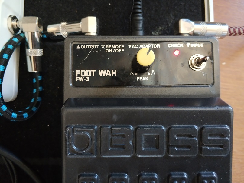
In a previous post (BOSS FW-3 Mods) I told how I did some basic mods to a BOSS FW-3 Wah pedal, which is basically a Cry Baby design with a potentiometer for varying the Q.
For the capacitor that controls the sweep range (C12), I chose a value of 0,022uF, to give the effect a very personal lower sweep range. I found it problematic in some situations, because the effectiveness of the variable band pass filter as a musical device is very dependent on the color of the signal that it encounters at its input. For instance, if I am using the brigde pickup in an already bright sounding guitar (tele or strat), playing high pitch notes, a low frequency sweep will let the sound almost without volume at the low end of the range. The same happens in the opposite situation – high sweep range with dark sounding pickups, or lower notes.
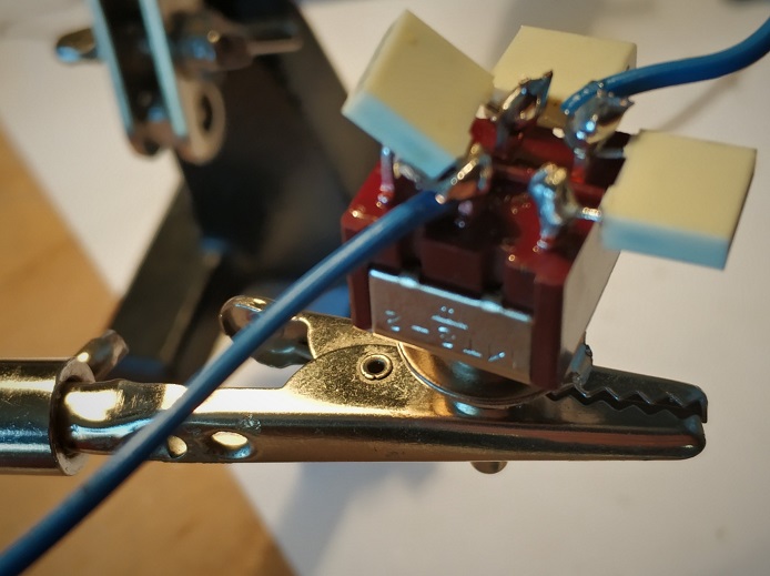
So, in order to have an all terrain wah effect, I have put a switch for alternating between three different values:
5nF – higher frequencies sweep range
10nF – the original one
20nF – lower frequencies sweep range
Given the behavior of a DPDT on-on-on switch, you can get those three values and their corresponding sweep range values (see https://www.electrosmash.com/crybaby-gcb-95) using three 10nF capacitors, this way:
Other values can be chosen, of course, to obtain more radical or subtle changes. For instance, with 10nF in the center, 56nF at right and 4.7nF on top you get:
3.2nF – very high range, good for a very bright guitar and higher notes
10nF – original sweep range
66nF – very low sweep, suitable for a bass guitar
The real life device, as built for this project:
As I mentioned in the previous post (BOSS FW-3 Mods), this pedal, apart from being a tank, has space enough inside for storing all the money I have. In this picture you can see how the DPDT switch fits inside the case:
In the main PCB, the cables from the switch are soldered instead of the original capacitor:
And the final result from the outside (the scratches and dents were already there, they are natural relic as this pedal has more than 20 years):
If you have any advice about the execution of the project, or simply have tried it, or in case you had any problem, please let me know in the comments below.
PD: si hacéis ese mod, ponedlo en los comentarios abajo. Me gustaría saber si la gente disfruta (o no) de mis mods.
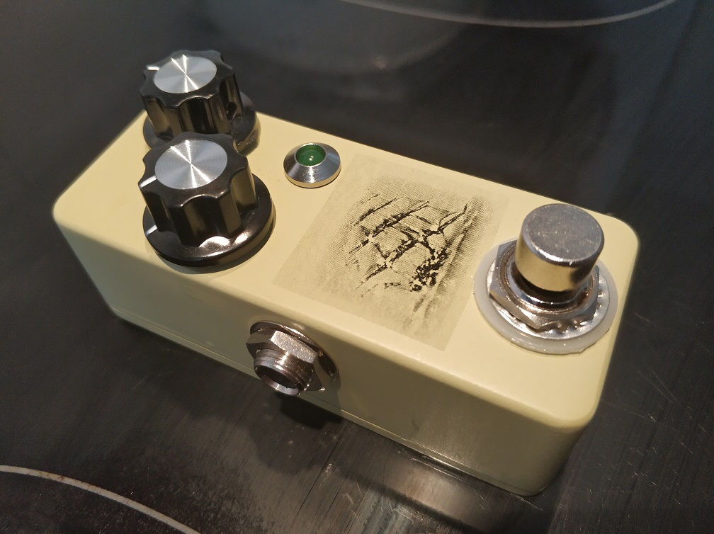
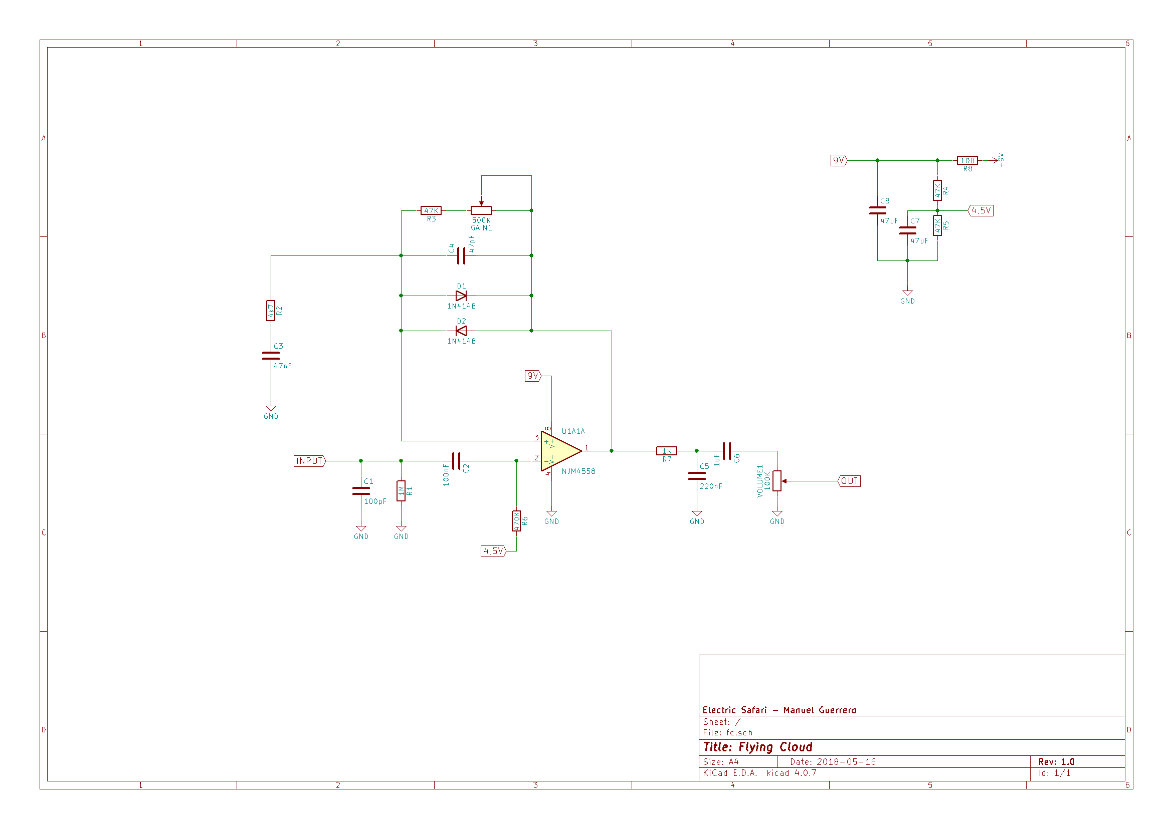
This new project is based on that archi-known japanese green overdrive. It is different in the component values (as many clones over there) and in the absence of tone control.
It all began as a simple overdrive circuit to be hidden inside a stratocaster, and it lived like that for a couple of days. For that purpose I didn’t need a tone control, because the guitar has its own one, and the amount of distortion was controlled by one of the strat pots (the middle one), while the other tone pot was controlling the tone of all pickups and also of the overdrive circuit.
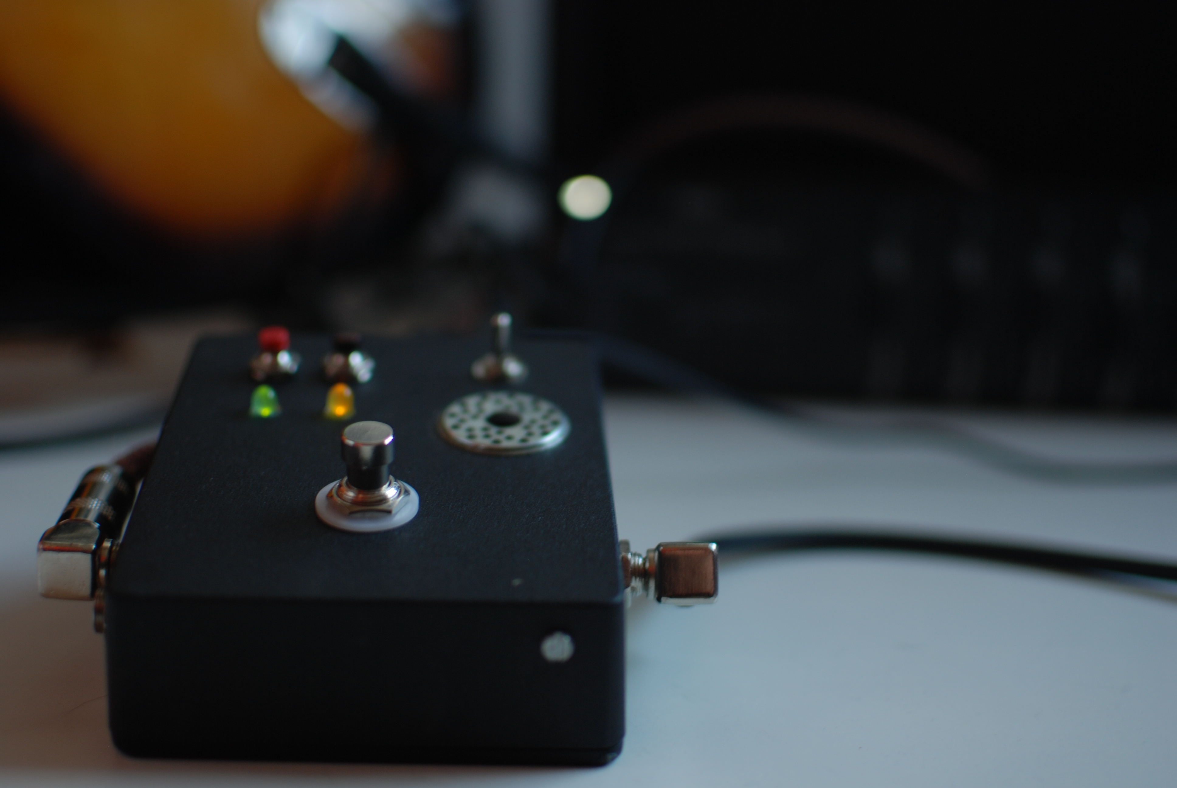
After trying the concept, I didn’t like the idea and removed the artifact from the guitar. But I liked the tone and tested it as an independent effect, even without the tone stage. Also, it would fit inside a 1590A enclosure, hence being a very practical device as a backup for my regular overdrive pedal or to be carried to jams or occasional gigs.
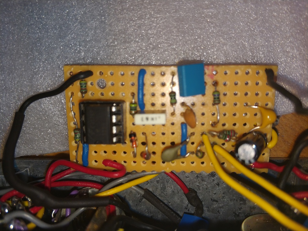
Here is the pcb (veroboard) after leaving its guitar life and before starting to be an effect pedal:
I can live without tone control, because almost all electric guitars has at least one tone control, I have an equalizer pedal and all amplifiers have a tone stack. I have adjusted the tone in the circuit to my preferences, but some components can be changed to shape the tone. On the other hand, the tone stack can be missed if you have other effects after this one that can be affected by its tone (stacking overdrives, phasers, etc).
Of course, feel free to use the concept and the schematics if you like it. If someone needs the veroboard layout I can prepare it and publish it also. Just buy me a beer and we’re even 🙂 I’m planning to record a demo for this pedal in the following days.
And why the name? The Flying Cloud was a fast clipper that sailed the seas in the XIX century. I like ships and this pedal is also a fast clipper (a soft clipper, to be more exact).
PD: the 220nF capacitor at the output of the operational amplifier can be removed for a less muddy sound. It is included in the original green overdrive and I had to included it at first in order to avoid oscillation with an LM348 as operational amplifier. After switching to 4558 kind of IC, the oscillation is not present even in abcense of that capacitor.
LM358 has a slew rate of 0.3V/uS, while JCR4558 has a slew rate of 1V/uS, which I think is the cause of that difference.
Now POP has a new feature, that I call “autoovation”. You start playing with your favorite effect, and when you stop playing, sometimes, if the pedal likes your performance, you hear an ovation from a digital audience.
Autoovation is made basically by detecting audio activity in input, then waiting for silence and playing a file randomly from a list of mp3 recorded ovations. For audio detection, silentjack (https://www.aelius.com/njh/silentjack/) was used (thanks Nicholas J Humfrey for your work and for letting me add a feature to your code).
This feature is just a joke, of course, but gives an idea of the kind of things that can be done with a device like this one. Think about things like backing tracks, automated rythm boxes, etc.
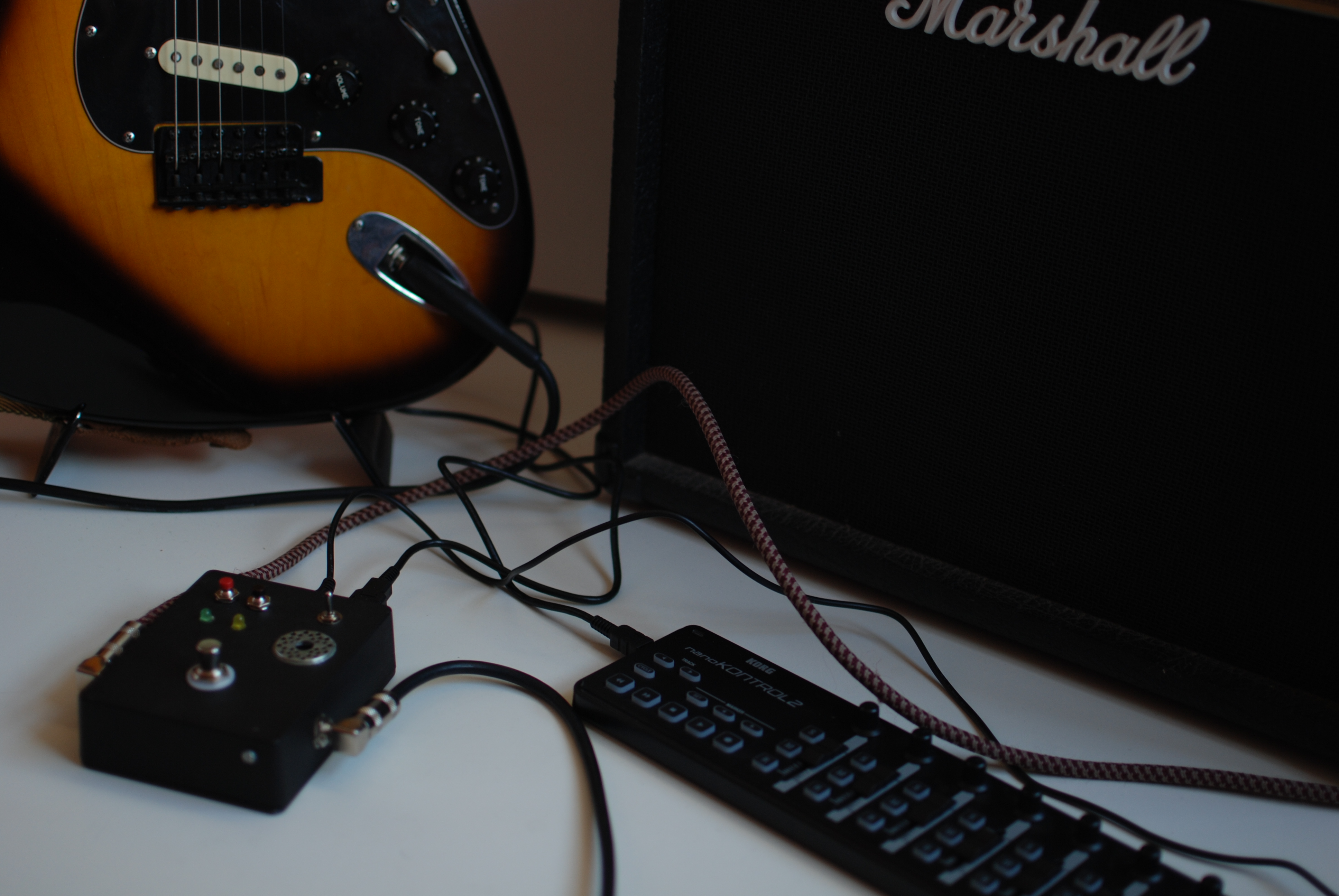
First recordings of POP through a Fender Blues Deluxe 40W AB tube amplifier. Camera is a GO Pro HERO. The amplifier is looking towards the wall in order to save our ears. Guitar is a Yamaha Revstar 420, I love it.
Impressions
Sound quality looks promising, though still I can hear some computing noise, specially when configuring a compressor or a distortion/overdrive. When using delay type effects, or reverb, noise is quite bearable.
I am using a 512 bytes buffer, and getting around 20ms of latency, still too much.
Some more research is needed to get the best from this unit, keeping in mind the limitations: CHIP board works at 1GHz, and sound card is integrated in the SoC, as long as I know.
This is my most recent project. Based upon the C.H.I.P. board form Next Thing Co, I have built a stompbox guitar digital pedal. These are its main features:
stereo output
true bypass
standard 9v input
three modes of operation
reset/shutdown button (the red one)
additional programmable button (the black one)
wifi, enabled inly in one of the modes
microusb input, for serial connection
USB input, where you can connect a MIDI controller, so effect parameters can be modified on the run
backup battery, so if you unplug the unit, you have the chance to shutdown gracefully
C.H.I.P board offers a good opportunity to build this kind of units because it has audio capture capabilities natively, without the need to plug an external (usually slow) USB sound card.
At this moment I am still doing tests, trying to improve sound quality. Some software stacks I have tested up to now:
Rakarrack on jack: unstable in this platform
Guitarix on jack: quite stable and very good sound quality, but a lot of CPU consumption. The good point is that you can configure and control the unit graphically, doing a SSH -X from a computer.
Supercollider on jack. Super-flexible, Supercollider is a programming language, so you can create any effect your imagination dictates. The problem is that I haven’t reached the sound quality I am looking for, maybe a SC expert can do.
LV2 plugins on jack, running with mod-host. With this combination I have got the best results, in a next post I will upload some sound clips. You can control parameters with a MIDI controller, and preset parameters. You can choose from a huge list of already programmed effects, and combine them in any order.
My current software configuration is based on LV2 on jack. I have programmed three modes of operation using the switch you can see at the right in the above picture:
switch up: double delay, controlling feedback and delay time of the two delays with a Korg Nanokontrol2 MIDI controller
switch middle: compressor, controlling attack, release and gain
switch down: reverb, controlling room dimensions and warmth. In this position, I activate wi-fi interface and sshd, so I can connect my computer and make changes, update the software, fix issues, etc.
Some advices for anyone looking for something similar:
WIFI
Wireless interface can be a problem if you enclose a computer inside an aluminium box, as is the case in this project. If you use a plastic box, you will have too much electromagnetic noise. For a compromise, I decided to drill a hole in the case, right above the wireless antenna. With an eight millimiters hole, and putting the unit not far from an access point, I am getting a quite good network access.
FAN
Another problem derived from the case is temperature. Without a fan, temperature was reaching 70 Celsius degrees. With a small 12V 25 mm fan, powered at 9V, temperature keeps stable at 51 degrees, even lower with wireless deactivated. I put the fun below the hole I had already done for wifi waves to escape the enclosure, as you can see in the pictures just below the switch.
For the rest of the software (LV2, mod-host) I will write a dedicated article.
SOUND INPUT AND OUTPUT
I have got the best results using the minijack input for audio capture, and board connectors for output. I have grounded the audio capture and output with the board connectors and at this moment there is almost no computer noise.
So I am very excited now with this project. My main concern now is sound quality and usability. I’ll write some additional posts with audio clips and new notes and advices. I would like to upload some schematics with the internals of the unit.
If someone is interested in more details about the project, or have some questions, please write some comments, or send me an email to manolonte@gmail.com.
Why does a melody sound good to us, to some of us but not to others? Why does a song sound sad while another one sounds glad or awfully dissonant? I don’t know, of course, but it seems to have to do with evocation of known melodies, cultural conventions and something in our brain that is still to be discovered.
Some time ago I was curious about what kind of sound resulted from the addition of two notes in a chord or a melody.
Let’s consider a root note, let’s say A440, known to have a frequency of 440Hz. The sound will be a sinusoidal wave, something that would seem like a flute.
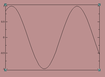
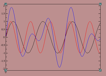
Now let’s add a perfect fifth. We’ll consider a perfect fifth to have a frequency = 3/2 of its tonic.
In black we have the tonic, in red perfect fifth and in blue the sum of both signals. What happened? The resulting sound is a signal with a frequency of 1/2 * 440Hz = 220 Hz.
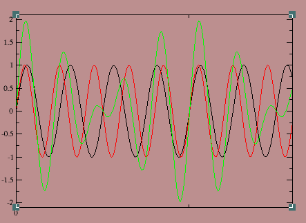
Now let’s consider our A flute and an added major third. There are several standards for major and minor third frequencies related to tonic (see https://en.wikipedia.org/wiki/Major_third) but for this exercise I will take the just intonation, in which the major third has a frequency of 5/4 multiplied by its tonic frequency.
In black the tonic, in red the major third and in green the sum. Now we have a resulting signal of 1/4 * 440Hz = 110 Hz.
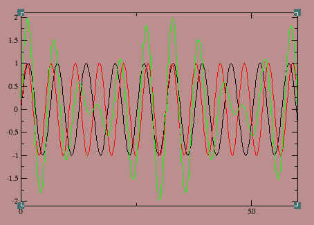
Now let’s add a minor third to the tonic. In just intonation, minor third has a relationship of 6/5 with its tonic frequency.
In black the tonic, in red the minor third and in green the addition of both. Now the resulting frequency is 1/5 * 440Hz = 88Hz
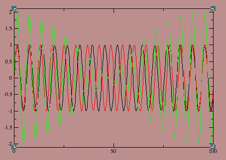
The last plot will consider a very dissonant note, a minor second, with a relationship with the tonic of 16:15.
The frequency of the resulting signal is 1/14 * 440Hz = 31.42Hz
Obviously, as the second note’s frequency approaches the tonic’s frequency, the resulting signal has a lower frequency.
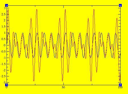
Now let’s take a chord. A major chord will be something like this:
In black the tonic and in red the addition of tonic, major third and perfect fifth. The resulting signal has a frequency of 1/4 * 440Hz=110Hz.
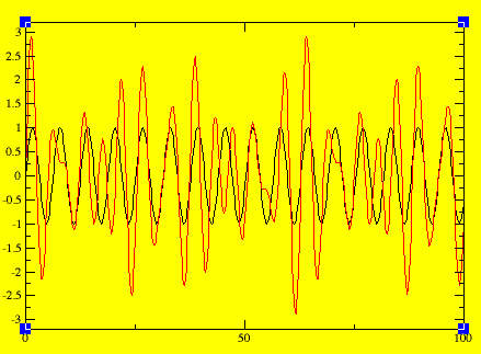
Now with A minor:
Now the resulting signal has a frequency of 1/10 * 440Hz.
Let’s summarize the results:
interval/chord
frequency
note
tonic
440Hz
A4
perfect 5th
220Hz
A3
major 3rd
110Hz
A2
minor 3rd
88Hz
~F2-F#2
minor 2nd
31.42Hz
~B0-C1
A major
110Hz
A2
A minor
44Hz
~F1-F#1
Perfect fifth and major 3rd have a curious property: when you add them to the tonic note, you produce a signal whose frequency has the same frequency of the same note in a different octave. However, when you add a minor 3rd or a minor second to the tonic, the resulting signal frequency has no relationship with any note.
I hope you have enjoyed this mathematical experiment and that it will make you think about intervals in a different way. But above all, please enjoy your favorite music, either thinking about intervals or not thinking at all.


 he design is very similar to TS9 but with some remarkable differences: